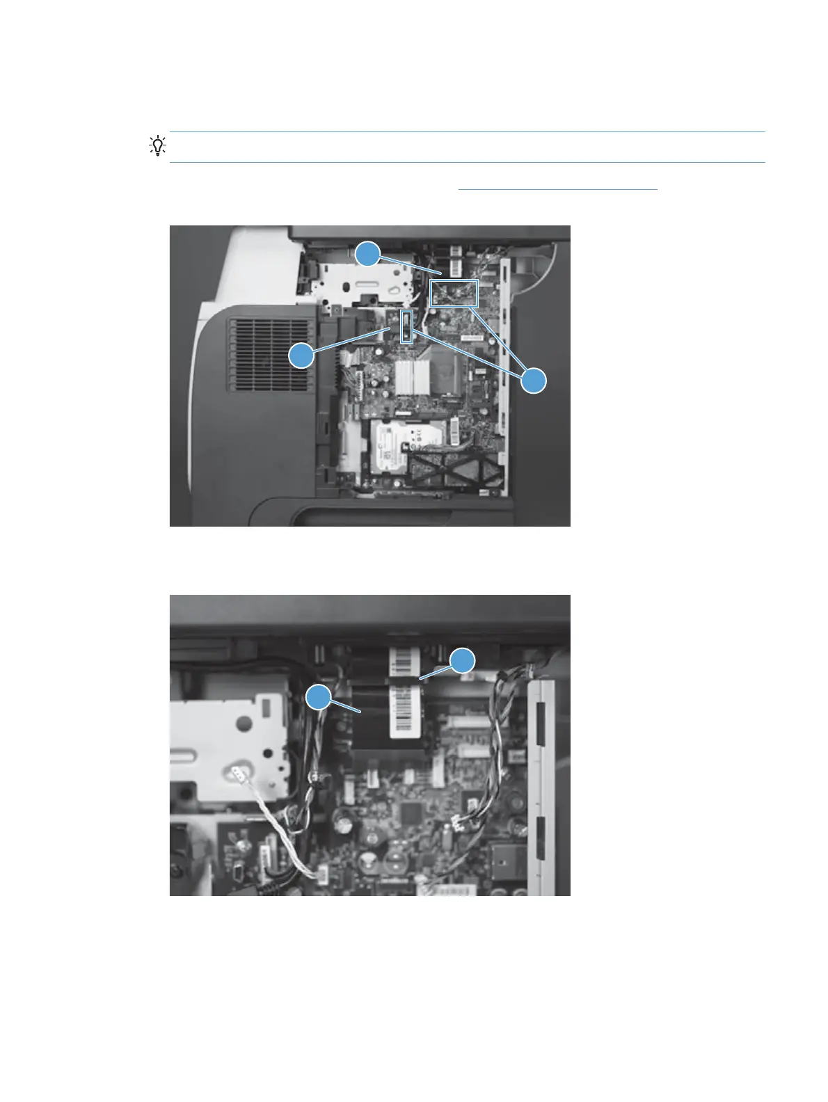
5. Disconnect five connectors (callout 1), one FFC (callout 2), and one USB cable (callout 3) from the
formatter.
Reinstallation tip If there are two FFC connectors, install the FFC in the bottom connector.
To locate the formatter connector locations, see Formatter connections on page 9.
Figure 1-140 Remove the image scanner whole unit kit (4 of 6)
2
3
1
6. Release the FFC (callout 1) from the retainer (callout 2).
Figure 1-141 Remove the image scanner whole unit kit (5 of 6)
2
1
ENWW
Removal and replacement procedures
93
 Loading...
