How to use the parts lists and diagrams
CAUTION: Be sure to order the correct part. When looking for part numbers for electrical
components, pay careful attention to the voltage that is listed. Doing so will make sure that the part
number selected is for the correct model.
NOTE: In this manual, the abbreviation “PCA” stands for “printed circuit-board assembly.”
Components described as a PCA might consist of a single circuit board or a circuit board plus other
parts, such as cables and sensors.
The figures in this chapter show the major subassemblies in the product and their component parts. A
parts list table follows each exploded view assembly diagram. Each table lists the item number, the
associated part number, and the description of each part. If a part is not listed in the table, then it is not
a field replacement unit (FRU).
Assembly locations
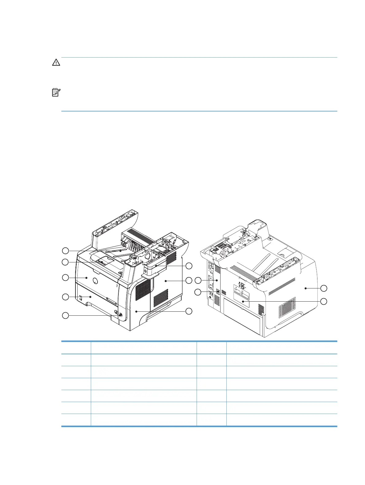
Base product (no optional trays or accessories)
Figure 2-1 Base product (no optional trays or accessories)
11
12
1
2
3
8
9
10
4
5
6
7
Item Description Item Description
1 Stapler cover 7 Right-rear cover
2 Formatter cover 8 Power switch
3Right cover 9Tray 2
4 Left cover 10 Tray 1
5 Rear door 11 Cartridge door
6 Power port 12 Face-down output bin
ENWW
How to use the parts lists and diagrams
173
 Loading...
