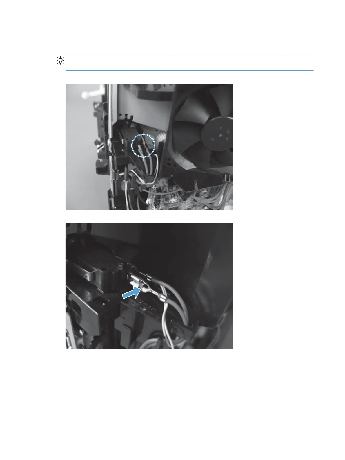
3. Release two tabs, and then carefully remove two wire connectors from the interlock switch
assembly.
TIP: It might be easier to release these connectors by first removing the interlock switch. See
Interlock switch assembly on page 114.
Figure 1-191 Remove the DC controller (2 of 6)
Figure 1-192 Remove the DC controller (3 of 6)
128 Chapter 1 Removal and replacement ENWW
 Loading...
