System Backplane
The system backplane contains the following components:
• The system clock generation logic
• The system reset generation logic
• DC-to-DC converters
• Power monitor logic
• Two local bus adapter (LBA) chips that create internal PCI buses for communicating with
the core I/O card
The backplane also contains connectors for attaching the cell boards, the PCI-X backplane, the
core I/O board set, SCSI cables, bulk power, chassis fans, the front panel display, intrusion
switches, and the system scan card. Unlike Superdome or the HP Integrity rx8640, there are no
Crossbar Chips (XBC) on the system backplane. The “crossbar-less” back-to-back CC connection
increases performance.
Only half of the core I/O board set connects to the system backplane. The MP/SCSI boards plug
into the backplane, while the LAN/SCSI boards plug into the PCI-X backplane.
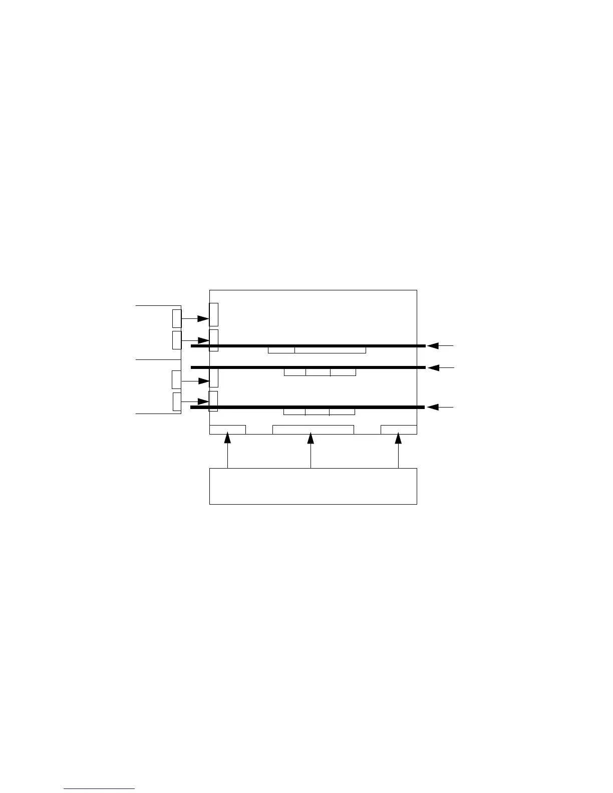
Figure 1-11 System Backplane Block Diagram
PCI-X backplane
Cell board 1
Cell board 0
System backplane
Bulk power supply
MP Core I/O
MP/SCSI
MP Core I/O
MP/SCSI
Cell boards are perpendicular
to the system backplane.
System Bacplane to PCI-X Backplane Connectivity
The PCI-X backplane uses two connectors for the SBA link bus and two connectors for the high
speed data signals and the manageability signals.
SBA link bus signals are routed through the system backplane to the cell controller on each
corresponding cell board.
The high speed data signals are routed from the SBA chips on the PCI-X backplane to the two
LBA PCI bus controllers on the system backplane.
Clocks and Reset
The system backplane contains reset and clock circuitry that propagates through the whole
system. The system backplane central clocks drive all major chip set clocks. The system central
clock circuitry features redundant, hot-swappable oscillators.
I/O Subsystem
The cell board to the PCI-X board path runs from the CC to the SBA, from the SBA to the ropes,
from the ropes to the LBA, and from the LBA to the PCI slots seen in Figure 1-12. The CC on cell
Detailed Server Description 29