Table 3-1 Wheel Kit Packing List (continued)
QuantityDescriptionPart Number
1Left front caster assemblyA6753-04006
1Left rear caster assemblyA6753-04007
4M4 x 0.7 8mm T15 steel zinc machine screw (Used to attach
each caster to the chassis)
0515-2478
1Plywood unloading rampA6093-44013
2Phillips head wood screw (Used to attach the ramp to the
pallet)
Not Applicable
Tools Required for Installation The following list provides the installer with the recommended
tools to perform the wheel kit installation.
• Diagonal side cutters
• Safety glasses
• Torx screwdriver with T-15 bit
• Phillips head screwdriver
WARNING! Wear protective glasses while cutting the plastic bands around the shipping
container. These bands are under tension. When cut, they can spring back and cause serious eye
injury.
Use the following procedure to install the wheel kit.
1. Cut and remove the polystrap bands securing the HP server to the pallet.
2. Lift the carton top from the cardboard tray resting on the pallet.
3. Remove the bezel kit carton and the top cushions from the pallet.
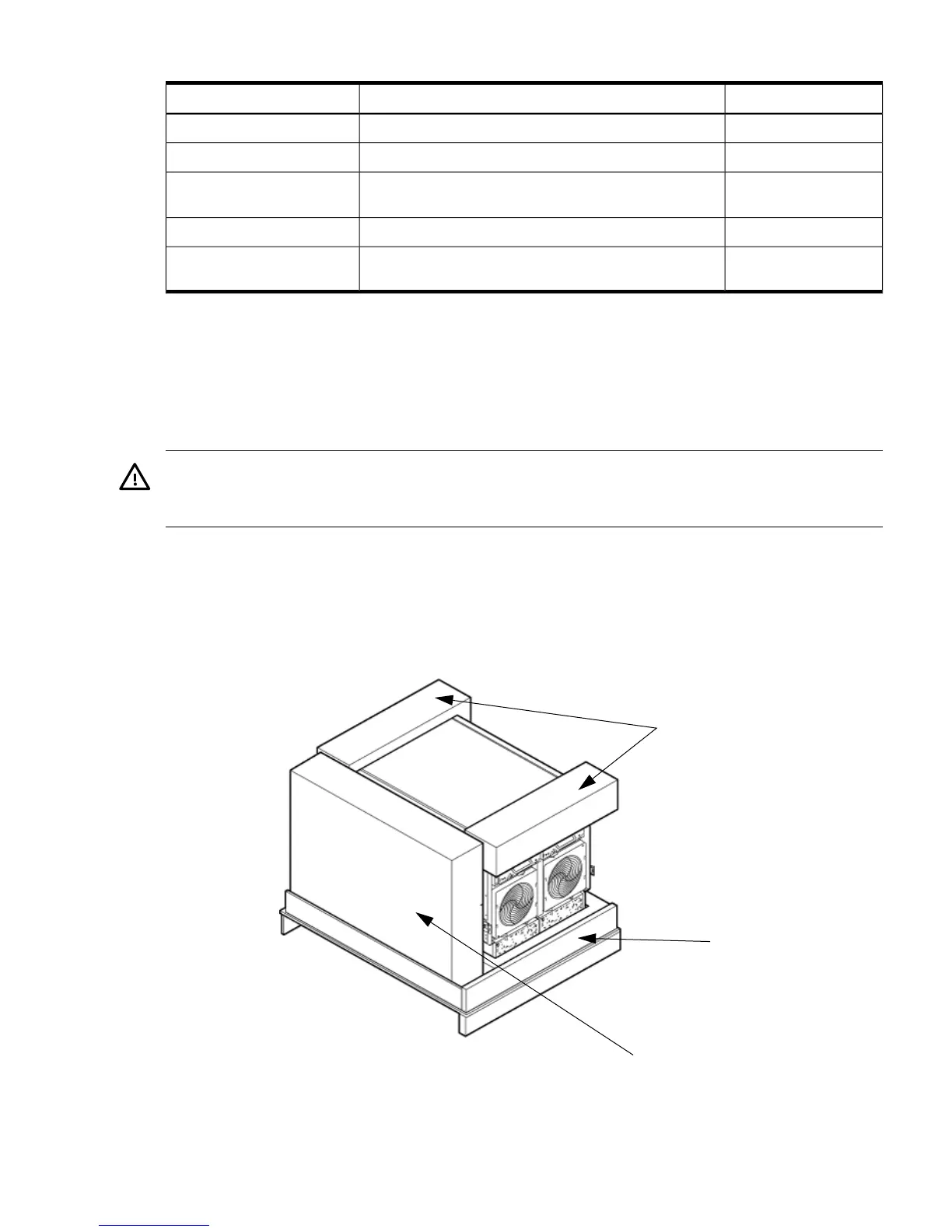
Figure 3-10 Component Locations
4. Unfold bottom cardboard tray.
5. Carefully tilt the server and place one of the foam blocks (A6093-44002) under the left side
of the server. Do not remove any other cushions until instructed to do so.
Wheel Kit Installation 53