2. Reduce the weight by removing the bulk power supplies and cell boards. Place each on an
ESD approved surface.
CAUTION: System damage can occur through improper removal and reinstallation of bulk
power supplies and cell boards. Refer to Chapter 6: Removing and Replacing Components,
for the correct procedures to remove and reinstall these components.
3. Remove the systems left and right side covers.
NOTE: The latest lift handles available for the 2-cell servers are symmetrical and can be
installed on either side of the server.
4. Locate one handle and ensure the two thumbscrews are removed from its front flange.
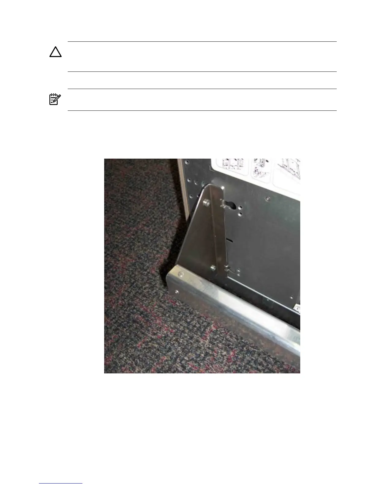
5. Insert the 2 protruding tabs on rear flange of handle into the slotted keyways in the server’s
chassis. See Figure 3-5.
Figure 3-5 Inserting Rear Handle Tabs into Chassis
6. Align the screw holes in the handle’s front flange with the rack mounting holes in the server’s
rack mount flange. Secure with the two thumbscrews. See Figure 3-6 (page 49).
48 Installing the Server