Figure 3-51 Position and cable routing out of the unit
● A humidity and temperature sensor should be installed 1.5 m above the oor.
● Each smart cooling product supports three cold aisle humidity and temperature sensors
and three hot aisle humidity and temperature sensors at most.
Setting the DIP Switch on the Humidity and Temperature Sensor
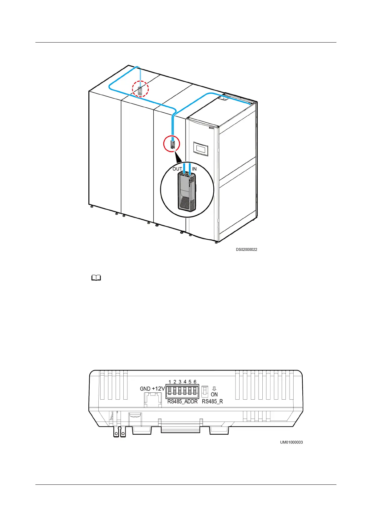
Figure 3-52 shows the DIP switch on a humidity and temperature sensor.
Figure 3-52 DIP switch
You need to set the DIP switch to change the communications address of sensors.
Table 3-17 describes the operation description.
NetCol5000-A(025, 035) In-row Air Cooled Smart
Cooling Product
User Manual (600 mm Width) 3 Installation Guide
Issue 17 (2020-10-22) Copyright © Huawei Technologies Co., Ltd. 80