15
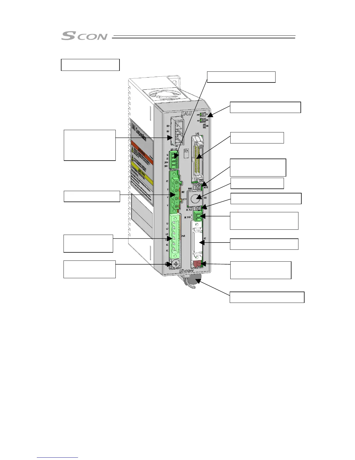
1) FG Connection Terminal [Refer to 1.7 Noise Elimination and Mounting Method.]
It is the terminal for the connection of ground cable to prevent electric shock and noise. It is
connected with the PE of the power connector in the controller.
2) Power Supply Connector (PWR) [Refer to 2.3.1 Wiring of Power Circuit.]
It is the connector to supply the power to the controller and to the control board.
3) Motor Connector (MOT) [Refer to 2.3.3 Connection to Actuator.]
It is the connector to connect the actuator's motor cable.
4) Regeneration Unit Connecting Connector (RB) [Refer to 2.3.6 Connectable Regenerative
Units.]
This connector is used to connect with an external regenerative unit.
5) System I/O Connector (SYS I/O) [Refer to 2.3.2 Wiring for Emergency Stop Circuit (System
I/O).]
This connector is used to connect with the emergency stop switch.
17) Absolute Battery Holder
16) Absolute Battery
Connector
15) Encoder Connector
14) Brake Power Supply
Connector
13) Brake Release Switch
12) SIO Connector
11) Operation Mode
Setting Switch
10) PIO Connector
8) Status Indicator LEDs
1) FG Connection
Terminal
2) Power Supply
Connector
3) Motor Connector
4) Regeneration
Unit
Connecting
Connector
5) System I/O Connector
SCON-CAL/CGAL