The SSA links must be configured as loops. The loop is connected to the internal
connectors at the SSA adapter card. These connectors
must
be a valid pair (that is,
A1 and A2, or B1 and B2); otherwise, the disk drive modules on the loop are not fully
configured, and the diagnostics fail. Operations to all the disk drive modules on a
particular loop can continue if that loop breaks at any one point.
Each pair of connectors has a green light that indicates the operational status of its
related loop:
Disk Drive Module Strings
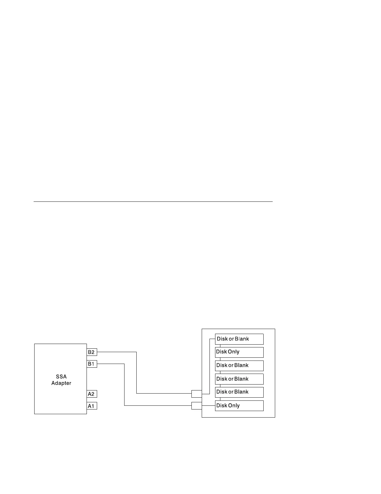
In the system unit, the disk drive modules are arranged in a string of 2 to 6 disk drive
modules. This string has its own two SSA connectors. This string is connected
through an internal SSA cable to a pair of connectors on the SSA adapter to make
an SSA loop. (The SSA cables provide the SSA links.)
Figure 3-2 shows the relationships between the SSA connectors and the disk drive
module string in a system unit.
Figure 3-2. A String of Disk Drive Modules
Status of Light Meaning
Off Both SSA connectors are inactive. If disk drive modules are connected to
these connectors, either those modules are failing, or their SSA links have not
been enabled.
Permanently on Both SSA links are active (normal operating condition).
Slow Flash Only one SSA link is active.
3-60 Service Guide
 Loading...

