9. Remove eight screws connecting the I/O planar to the rear of the system. Note
that the screws in the SCSI connector are black.
10. Remove 12 screws from the I/O planar.
11. Remove I/O planar.
Note: The system card can be removed without removing the I/O planar.
However, you must remove the system card before removing the I/O planar.
Replacement
Replace in reverse order.
Note: Be sure to install the two black screws in the SCSI connector.
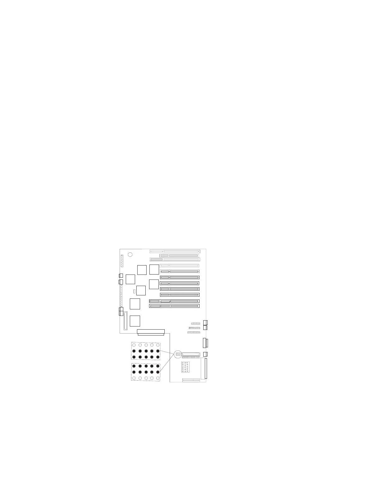
Verify that the security jumpers (J16) are in the correct position (same as the
replaced I/O planar).
J47
J41
J50
J1
J2
J3
J4
J5
J6
J7
J8P
J8I
J9I
J9P
External SCSI Port
Enabled
External SCSI Port
Disanabled
6-34 Service Guide
 Loading...

