3.5-inch model: There are the right EIA assembly and the left EIA assembly on
the server, use the following steps to remove them.
For the right EIA assembly
1. Read the safety information that begins on “Safety” on page vii and
“Installation guidelines” on page 283.
2. Turn off the server and peripheral devices, and disconnect the power cord and
all external cables.
3. Remove the top cover (see “Removing the top cover” on page 146).
4. Remove the fan cage assembly (see “Removing the fan cage assembly” on
page 172).
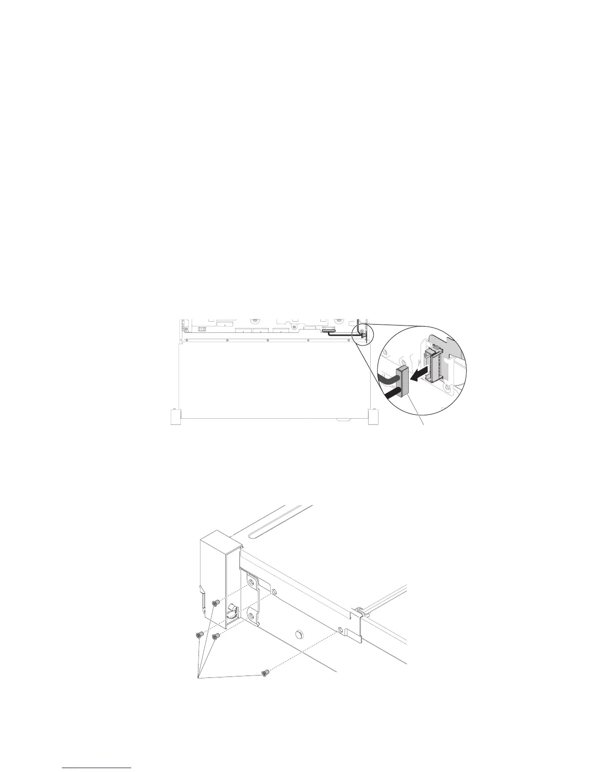
5. Disconnect the front USB/operator information panel cables from the
connector mounted on the chassis side wall.
Note: Disengage all latches, release tabs or locks on cable connectors when
you disconnect all cables from the system board. Failing to release them before
removing the cables will damage the cable sockets on the system board. The
cable sockets on the system board are fragile. Any damage to the cable sockets
may require replacing the system board.
6. Loosen screws and remove them.
Front USB / operator
information panel cable
Figure 147. Front USB/operator information panel cable removal
Screws
Figure 148. Screw removal
Chapter 5. Removing and replacing components 211
 Loading...


