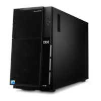
rotate the cage inward until it sits into place 3.
1
3
1
2
10. Close the latches on the chassis.
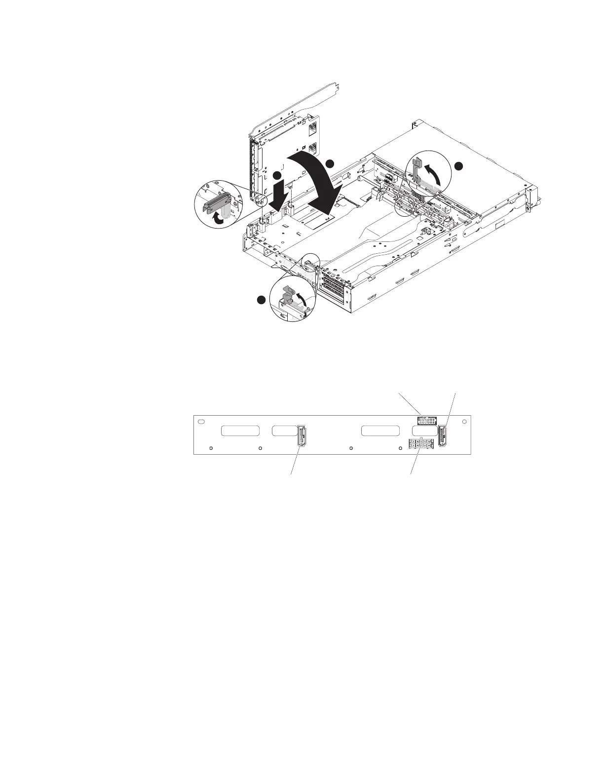
11. Connect the LED signal cable and SATA cables from the option package into
the backplane assembly on the rear hard disk drive cage.
SATA 0 connector
LED signal
connector
Power connectorSATA 1 connector
12. Insert the backplane assembly from the option package onto the rear hard disk
drive cage (see “Installing the hot-swap backplane on the optional rear hard
disk drive cage” on page 187).
13. Remove the system fan cage to obtain more room:
a. Grasp the system fan cage by the blue grip points.
b. Press the retention latches toward each other; then, lift the system fan
cage out and put it on the bulkhead.
Chapter 5. Removing and replacing server components 207
 Loading...