18
CONNECTOR INFORMATION
18-3
ACC socket (Continued)
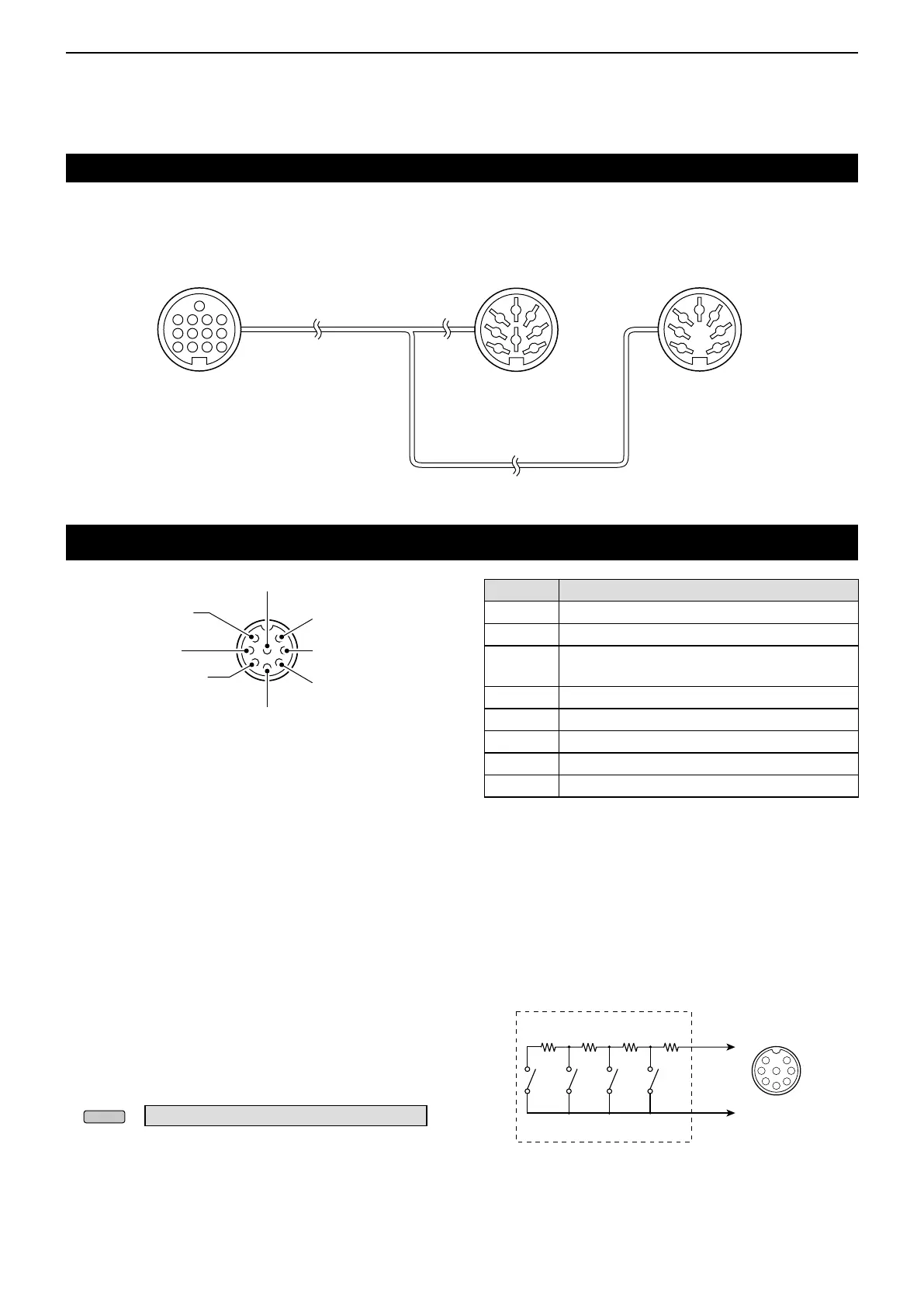
Microphone connector
D OPC-599 ACC conversion cable pin assignments
1 2 3 4
8
8
765
9
10 11 12
13
1
2
3
4
7
6
5
1
2
3
4
7
6
5
[ACC] socket
(IC-7300)
ACC 1 ACC 2
q FSKK
w GND
e SEND
r MOD
t AF
y SQLS
u 13.8 V
i ALC
q 8 V
w GND
e SEND
r BAND
t ALC
y —
u 13.8 V
q Microphone input
w +8 V DC output
e Frequency up/down
r Squelch line output
t PTT
y GND (PTT ground)
u GND
(Microphone ground)
i AF output
PIN No. DESCRIPTION
q
Microphone input (Impedance: 600 Ω)
w
+8 V DC output (Maximum 10 mA)
e
Up: Ground
Down: Ground through 470 Ω
r
Grounded when the squelch opens.
t
PTT
y
PTT ground
u
Microphone ground
i
AF output (varies with the [AF] control.)
D External keypad
A circuit is used to output memory content from 4
memories. You can output desired memory content
such as that from a CW Memory keyer (M1 ~ M4),
Voice memory (T1 ~ T4), RTTY Memory (RT1 ~ RT4)
to be transmitted.
z Push a switch to send the memory information.
z Hold down the switch for 1 second to repeatedly
send the memory information.
L To use the external keypad, turn ON the following
items in the CONNECTORS set screen. (p. 12-8)
» SET > Connectors > External Keypad
• VOICE: ON
• KEYER: ON
• RTTY: ON
L The External keypad is not supplied by Icom. (User
supplied)
The OPC-599 ACC conversion cable connects
between a 13 pin [ACC] socket and 7 pin and 8 pin
sockets.
PINe
PINy
1.5 kø
±
5%
1.5 kø
±
5%
2.2 kø
±
5%
4.7 kø
±
5%
S1S2S3S4
1
2
3
4
5
6
7
8
MIC
External keypad
Front panel
view
[MIC]
connector
Front panel view