!7 NOISE BLANKER SWITCH [NB] (p. 60)
➥
Push to turn the Noise Blanker ON or OFF. The
Noise Blanker reduces pulse-type noise such as
that generated by vehicle ignition systems. The
Noise Blanker cannot be used in the FM mode,
and is not effective for non-pulse-type noise.
•“NB”appearswhentheNoiseBlankerisON.
➥ Hold down for 1 second to display the “NB”
screen. Push to return to the previous screen
display.
!8 NOISE BLANKER LEVEL CONTROL [NB]
(outer control; p. 60)
Rotate to adjust the noise blanker threshold level
when the Noise Blanker is ON. Set for maximum
readability.
•Tousethiscontrol,rstpush[NB](!7).
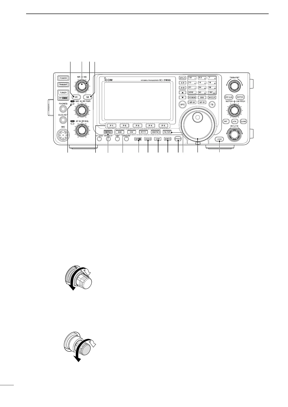
Increases
Decreases
!9 NOISE REDUCTION LEVEL CONTROL [NR]
(inner control; p. 61)
Rotate to adjust the DSP noise reduction level
when the Noise Reduction is ON. Set for maximum
readability.
•Tousethiscontrol,rstpush[NR](@0).
Increases
Decreases
@0 NOISE REDUCTION SWITCH [NR] (p. 61)
Push to turn DSP Noise Reduction ON or OFF.
•“NR”appearswhenNoiseReductionisON.
@1 TX INDICATOR
Lights red while transmitting.
@2 FUNCTION SWITCHES [F1]–[F5] (pp. 13, 14)
Push to select the function which is indicated on the
LCD display above each switch.
•Thefunctionsvary,dependingontheselectedmenu
and the operating mode.
@3 MENU SWITCH [MENU] (pp. 13, 14)
➥ Push to change the set of functions assigned to
switches ([F-1] to [F-5]).
•Togglesbetweenthefunctionmenus,M1(Menu1)
and M2 (Menu 2).
➥ Hold down for 1 second to enter the Set mode.
Push to return to the previous screen display.
@4 MODE SWITCHES
Push to select your desired operating mode. (p. 31)
•Thebuilt-inspeechsynthesizerannouncestheselected
mode when the “SPEECH [MODE] SW” item is set to
“ON” in the Set mode. (p. 87)
[SSB]
➥ Push to alternately select the USB or LSB
modes.
•“USB”or“LSB”appears.
➥ In the SSB mode, hold down for 1 second to se-
lect the SSB data mode (USB-D, LSB-D).
•“D” appears in addition to “USB” or “LSB.”
➥ In the SSB data mode, push to return to the nor-
mal SSB mode.
[CW]
Push to alternately select the CW and CW-R (CW
reverse)
modes.
•“CW”or“CW-R”appears.
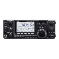
■ Front panel (continued)
3
1
PANEL DESCRIPTION
@1
@5 @6 @7 @8 @9
#1
#0
#2
@0 !9 !8 !7
@4
@2
@3