Home
ICS
Controller
Tunnel Master Jr
ICS Tunnel Master Jr User Manual
4
of 1
of 1 rating
108 pages
Give review
Manual
Specs
To Next Page
To Next Page
To Previous Page
To Previous Page
Loading...
User Manual—Version 3.0
Tunnel Master
Jr.
2 Relay Boxes, 2 Keypads, 2 Printers
January 2016
101
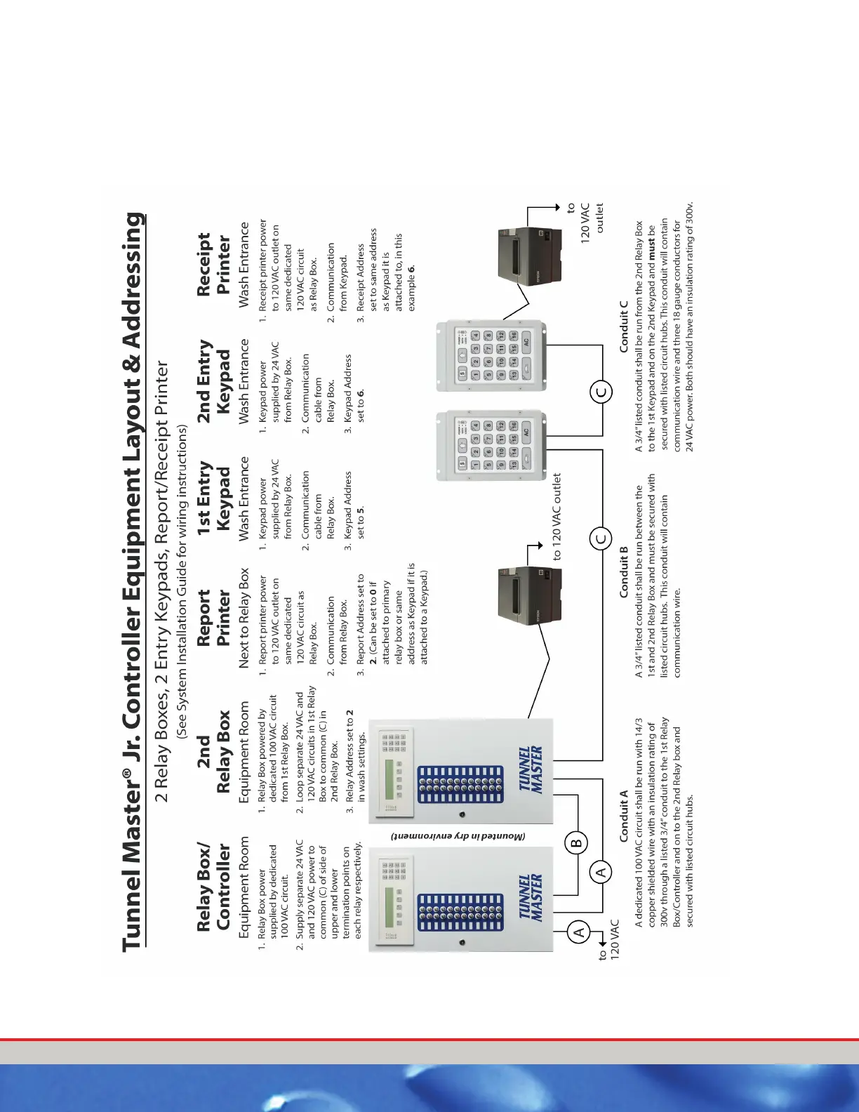
APPENDIX C:
2 Relay Boxes, 2 Keypads, 2 Printers
Figur
e 28. Appendix C - 2 Relay Bo
xes/2 Entranc
e Ke
ypads/Report Receipt Printer
100
102
Table of Contents
Default Chapter
3
Table of Contents
3
Chapter 1 Introduction
11
Version Considerations
11
Related Documents
11
Audience
11
Controller Features
12
Chapter 2 System Hardware and Installation
13
Audience
13
Purpose
13
Resetting Default Configuration Settings
14
Rules for Installation
14
Warning Marking
15
Output Overview
15
24 Outputs
15
Figure 1. Front Panel
15
Relay Box Installation
16
Relay Box Mounting
16
Relay Box Wiring
16
Relay Box Interior
18
Figure 2. Low Voltage Layout Wiring Diagram
18
Figure 3. Relay Box Interior Components
19
Pulse/Proximity Switch Wiring
20
Pulse/Proximity Switch Wiring
21
Figure 4. Pulse/Proximity Switch Wiring
21
Gate Switch (Electric Eye) Wiring
22
Gate Eye Switch Wiring
23
Figure 5. Gate Eye (Switch) Wiring
23
Tire Switch Wiring
24
Figure 6. Tire Switch Wiring
24
Entrance Management System Wiring
25
Entrance Management System Wiring
26
Roller Locator Wiring
26
Figure 7. Entrance Management Overview and Wiring Diagram
26
Conveyor Roller Locator Cross Section Diagram
27
Figure 8. Roller Locator Cross Section Diagram
27
Figure 9. Roller Locator Wiring
28
Roller Locator Wiring
28
Panic Stop Circuit Wiring
29
Panic Stop Wiring
30
Figure 10. Panic Stop Circuit Wiring
30
Anti-Collision Wiring
31
Anti-Collision Wiring
32
Figure 11. Anti-Collision Wiring
32
Input Wiring Summary
33
Figure 12. Inputs
33
Push Button Wiring
34
Push Button Wiring 1 Row 8 Columns
35
Figure 13. Push Button Wiring 1 Row 8 Columns
35
Push Button Wiring First 8 Buttons
36
Figure 14. Push Button Wiring First 8 Buttons
36
Push Button Wiring for Second 8 Buttons
37
Figure 15. Push Button Wiring for Second 8 Buttons
37
Relay Box Jumper Settings
38
Figure 16. Relay Jumper Box Settings
38
Table 1. Relay Box Circuit Descriptions
39
DIP Switch Settings
40
Figure 17. DIP Switch Located on Inside of Relay Box Door
40
Table 2. DIP Switch Normal Settings/Functions
40
Chapter 3 Operating Procedures
41
Main Wash Menu
41
Table 3. Main Wash Menu
41
Wet down Wash
42
Table 4. Wet down Wash Instructions
42
Chapter 4 Wash Configuration
43
Relay Box Display Keypad
44
Figure 18. Main Screen Display and Keypad
44
Set Password
45
Table 5. Relay Box Display and Keypad Indicator Light Descriptions
45
Table 6. Change the System Password Instructions
46
Access a Password Protected Menu
47
Table 7. Add Password Instructions
47
Configure Wash Menu
48
Wash Setting Descriptions
48
Table 8. Configure Wash Menu
48
Table 9. Wash Settings Menu
49
Set Date Time
52
Table 10. Set Date and Time Instructions
53
Configure Wash Settings
54
Table 11. Configure Wash Settings
54
About Countdown Times
55
Outputs
56
Table 12. Outputs Descriptions
56
Output Settings
58
Table 13. Output Settings
58
Table 14. Services Menu Item Descriptions
60
Table 15. Change or Set Services Instructions
61
Assign Outputs to Services
63
Table 16. Assign Outputs to Services Instructions
63
Chapter 5 Entrance Keypad
65
Entrance Keypad Functions
66
Figure 19. Entrance Keypad
66
Table 17. Entrance Keypad Buttons
67
Entrance Keypad to Process Vehicles (Non-Stacking)
68
Table 18. Process Vehicles (Non-Stacking)
68
Entrance Keypad to Process Vehicles (Stack)
69
Change Service And/Or Add Retract
69
Table 19. Process Vehicles Stack Instructions
69
Add a Car to Stack
70
Remove a Car from Stack
70
View Service Counts
71
Table 20. View Service Counts Instructions
71
Shift Break
72
Bump a Shift or Manually Close Current Shift
73
Table 21. Manually Close or Bump the Current Shift Instructions
73
User Manual-Version
75
Communication and Keypad Installation
75
Tunnel Master Jr
75
Entrance Keypad Mounting and Installation
75
Entrance Keypad Mounting
75
Entrance Keypad Wiring
75
Figure 20. Keypad Connectors (Keypad Board)
76
Figure 21. AC Power Terminations
77
Figure 22. Communication Cable Termination Diagram
79
Second Entrance Keypad Mounting and Installation
80
Second Entrance Keypad Mounting
80
Second Entrance Keypad Wiring
80
Table 22. 120 VAC Terminations
80
Entrance Keypad Jumper Settings
82
Figure 23. Keypad Circuit Board Jumper Settings
82
Table 23. Comm Cable Terminations
82
Entrance Keypad DIP Switch Settings
83
Figure 24. DIP Switch
83
Table 24. Default Jumper Settings
83
Table 25. DIP Switch Settings
84
Chapter 7 Optional Report/Receipt Printer Installation
85
Mounting and Installation of Report/Receipt Printer
86
Report Printer Mounting
86
Report Printer Wiring
86
Figure 25. Epson Dot Matrix Report/Receipt Printer
86
Chapter 8 Trouble Shooting
89
System Diagnosis
89
Entrance Keypad
89
Wash Controller Response
89
Wash Controller Input Check
90
Entrance Keypad Diagnostics
91
Table 26. Relay Box Troubleshooting
91
Table 27. Entrance Keypad Troubleshooting
92
Table 28. Miscellaneous Troubleshooting
93
Figure 26. Appendix A - 1 Relay Box/1 Entrance Keypad/1 Receipt Printer
97
Figure 27. Appendix B - 2 Relay Boxes/1 Entrance Keypad/1 Receipt Report Printer
99
Figure 28. Appendix C - 2 Relay Boxes/2 Entrance Keypads/Report Receipt Printer
101
Change History
107
Other manuals for ICS Tunnel Master Jr
Manual
83 pages
4
Based on 1 rating
Ask a question
Give review
Questions and Answers:
Need help?
Do you have a question about the ICS Tunnel Master Jr and is the answer not in the manual?
Ask a question
ICS Tunnel Master Jr Specifications
General
Brand
ICS
Model
Tunnel Master Jr
Category
Controller
Language
English