EasyManuals Logo

ICS Tunnel Master Jr User Manual

ICS Tunnel Master Jr
108 pages
To Next Page IconTo Next Page
To Previous Page IconTo Previous Page
Page #18 background imageLoading...
Page #18 background image
System Hardware and Installation Tunnel Master
Jr. User Manual—Version 3.0
18 January 2016
.
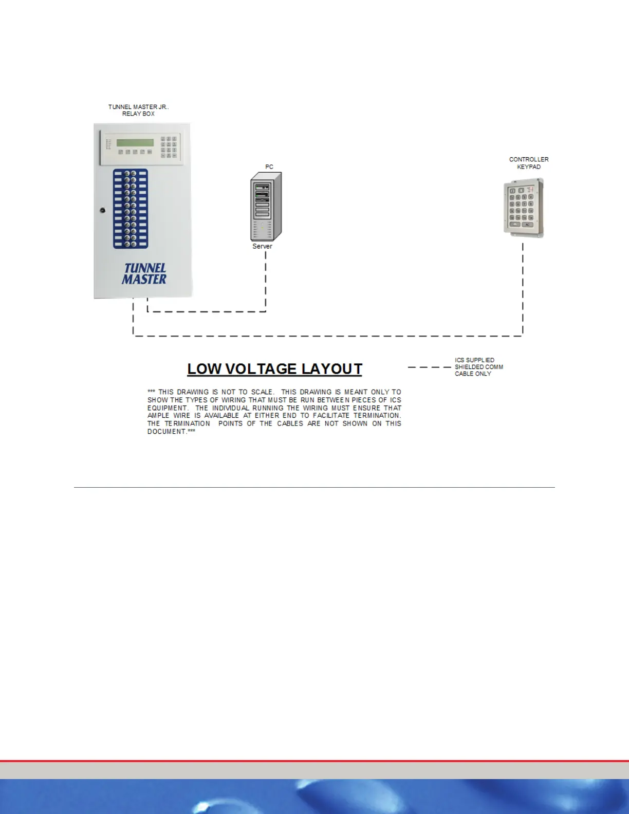
Figure 2. Low Voltage Layout Wiring Diagram
RELAY BOX INTERIOR
Each relay has circuits to control both 24 VAC and/or 120 VAC simultaneously
so that a service sign as well as the service solenoid can be operated from
the same relay.
Plug in relays for ease of serviceability.
Each relay has
2 fuses.
Built in spare fuses and fuse tester near the center of the box.
Each relay can be programmed to flash, eliminating the need for field
installed flashing relays for signs.

Table of Contents

Other manuals for ICS Tunnel Master Jr

Questions and Answers:

Question and Answer IconNeed help?

Do you have a question about the ICS Tunnel Master Jr and is the answer not in the manual?

ICS Tunnel Master Jr Specifications

General IconGeneral
BrandICS
ModelTunnel Master Jr
CategoryController
LanguageEnglish