User Manual—Version 3.0 Tunnel Master
Jr. Communication and Keypad Installation
January 2016 83
In Figure23, “Keypad Circuit Board Jumper Settings,”, the jumper functions
are displayed with their normal settings. By default, the keypad is address 5.
There is no reason to change this unless advised by ICS. If you have two
keypads, you should address the second
as address 6.
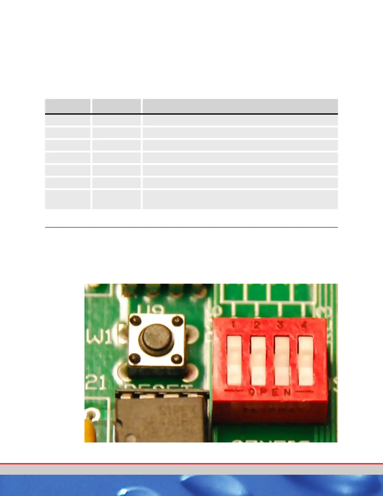
ENTRANCE KEYPAD DIP SWITCH SETTINGS
The following picture and table will show the Entrance Keypad DIP switch
and the various settings that may be used.
NOTE: The OFF position is away from the word Config on the circuit board.
The following picture shows the Entrance Keypad DIP Switch.
Figure 24. DIP Switch
Table 24: Default Jumper Settings
Jumper
J1 ON Reserved Jumper; ALWAYS ON
J2 ON Reserved Jumper; ALWAYS ON
J3 1 and 2 E-Prom Chip Enable; Jumper Down next to CE
J4 ON Ground Jumper
J5 OFF Biasing Resistor High (+)
J6 OFF Biasing Resistor Low (-)
J7 ON Terminating Resistor. Set to ON if it is the first or last device
in the network.

 Loading...