User Manual—Version 3.0 Tunnel Master
Jr. System Hardware and Installation
January 2016 19
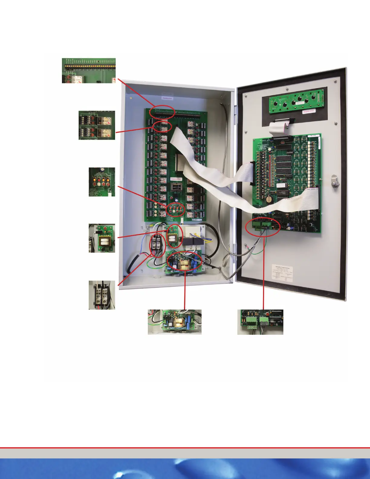
Figure 3. Relay Box Interior Components
ermination points for Pulse,
Gate, Tire, and Panic Circuits.
Plug in relays for ease of
serviceability. Each relay has
two fuses (24 VAC and 120
VAC).
Built in spare fuses
and fuse tester.
Power In
12 VAC transformer
powers the Relay
circuit board on
ly.
WARNING:
DO NOT Power any
other devices from this
transformer!
Power Conditioner
Board
Comm Cable Terminal Blocks for 16 button
Entrance Keypad and other TMJ relay box.
 Loading...
