Communication and Keypad Installation Tunnel Master
Jr. User Manual—Version 3.0
76 January 2016
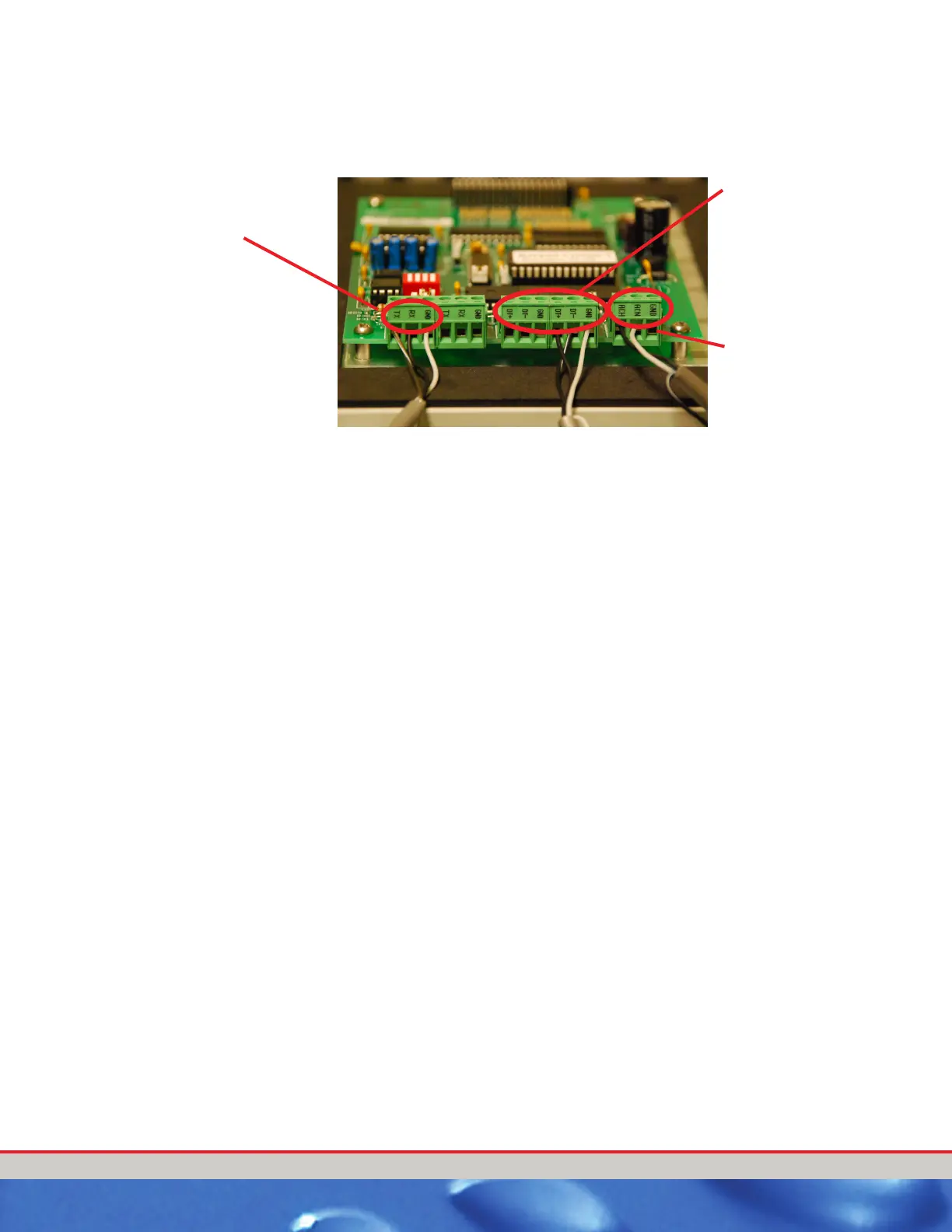
The following picture shows the connection points for the various
components.
Figure 20. Keypad Connectors (Keypad Board)
There is a terminal block (POWER), located on the keypad circuit board
labeled with ACH, ACN and GND, for Load, Neutral and Ground,
respectively. Terminations for the 3 – 18AWG wires should be torqued to
20 pound-inches (2.3 n-m.) Over torquing
may cause enclosure breakage.
The equipped with a 12 VAC transformer, which is to be used to power the
Entrance Keypad. If a second transformer is present, the 12 VAC
terminations must be made as follows from the separate transformer. If
there is only one
transformer, terminate power from it.
Optional Pole Display
screen termination
points
Communications wire
termination points.
You can use either
terminal block. In a
second keypad,
you would use serial.
12 VAC termination
block
 Loading...
