Communication and Keypad Installation Tunnel Master
Jr. User Manual—Version 3.0
82 January 2016
Comm cable terminations must be made as in the following table.
ENTRANCE KEYPAD JUMPER SETTINGS
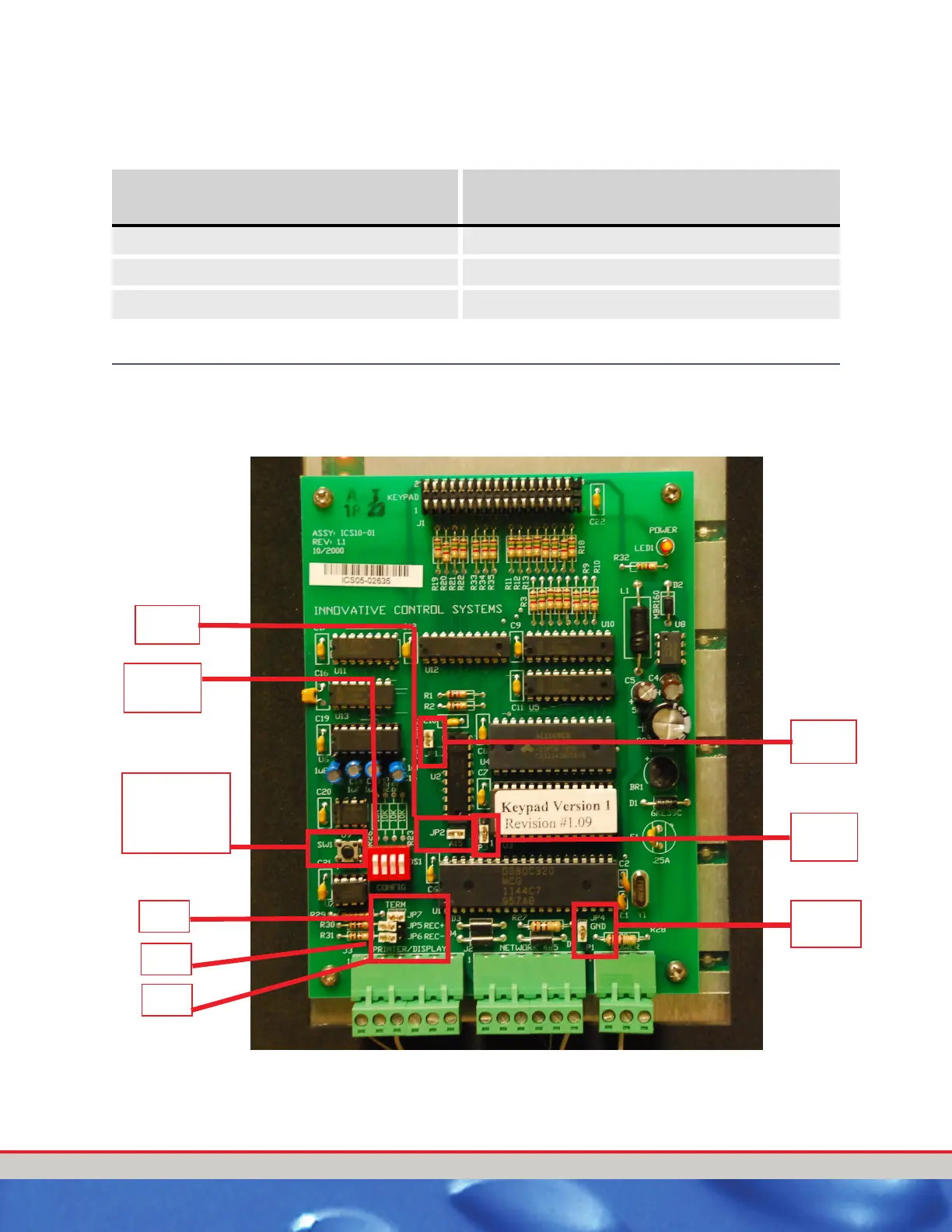
The following figure shows the Entrance Keypad circuit board and location of
the various jumpers on the Entrance Keypad circuit board.
Figure 23. Keypad Circuit Board Jumper Settings
Table 23: Comm Cable Terminations
First Entrance Keypad
(Either Connector)
Second Entrance Keypad
(Either Connector)
DT+ DT+
DT- DT-
GND GND
JP7
JP5
JP6
(SW1) Circuit
Board Reset
button
JP4
JP2
DIP
Switch
JP3
JP1
 Loading...