System Hardware and Installation Tunnel Master
Jr. User Manual—Version 3.0
30 January 2016
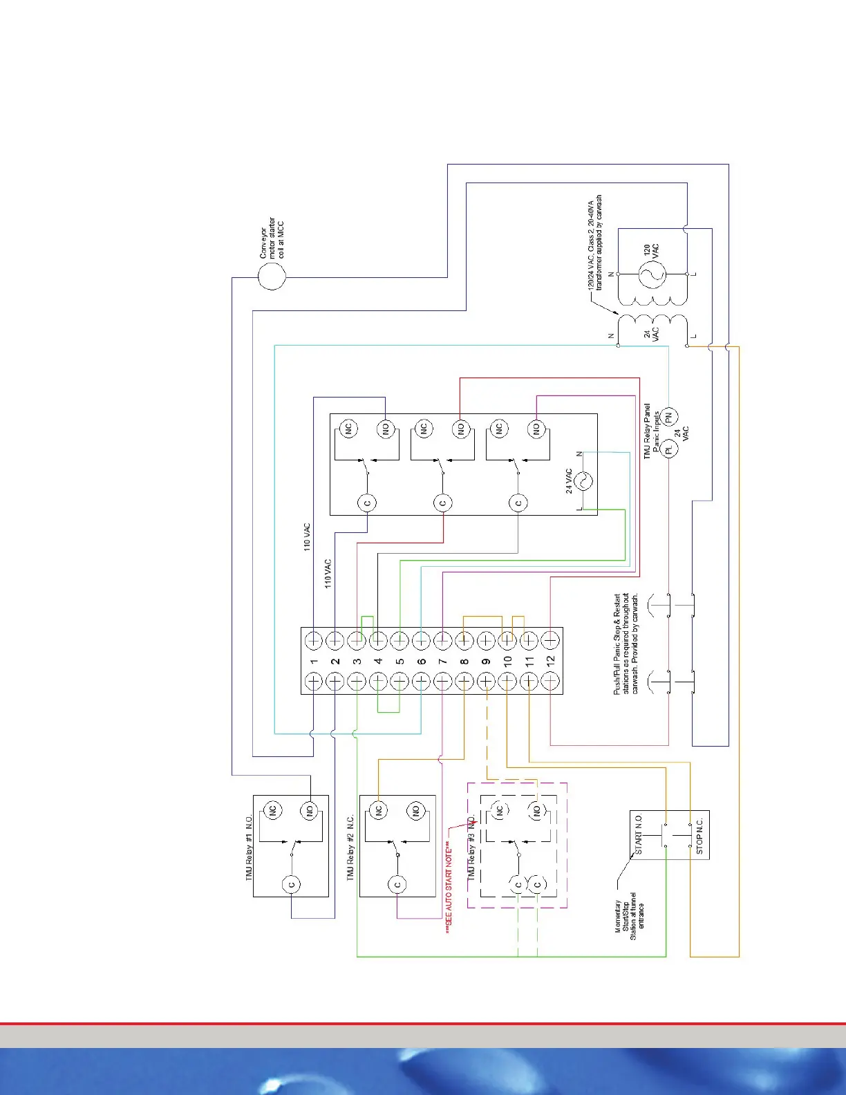
Panic Stop Wiring
Figure 10. Panic Stop Circuit Wiring
PROGRAMMING
Relay #1 Conveyor Enable 0, 0, 0, AC, N, N, N, 0
Relay #2 Auto Stop 0, 0, 0, A, AC, N, N, N, 0
Relay #3 Conveyor Auto Start 0, 0, 0, 0, AC, N, N, N, 0
Relay #4 Horn 3,1, 0, H, AC, N, N, N, 0
Panic Wash is set to “Y”
** In Relay #4 that start time is the length of time that the horn
sounds and the extend time is the delay that the conveyor will
start after the horn ends.

 Loading...