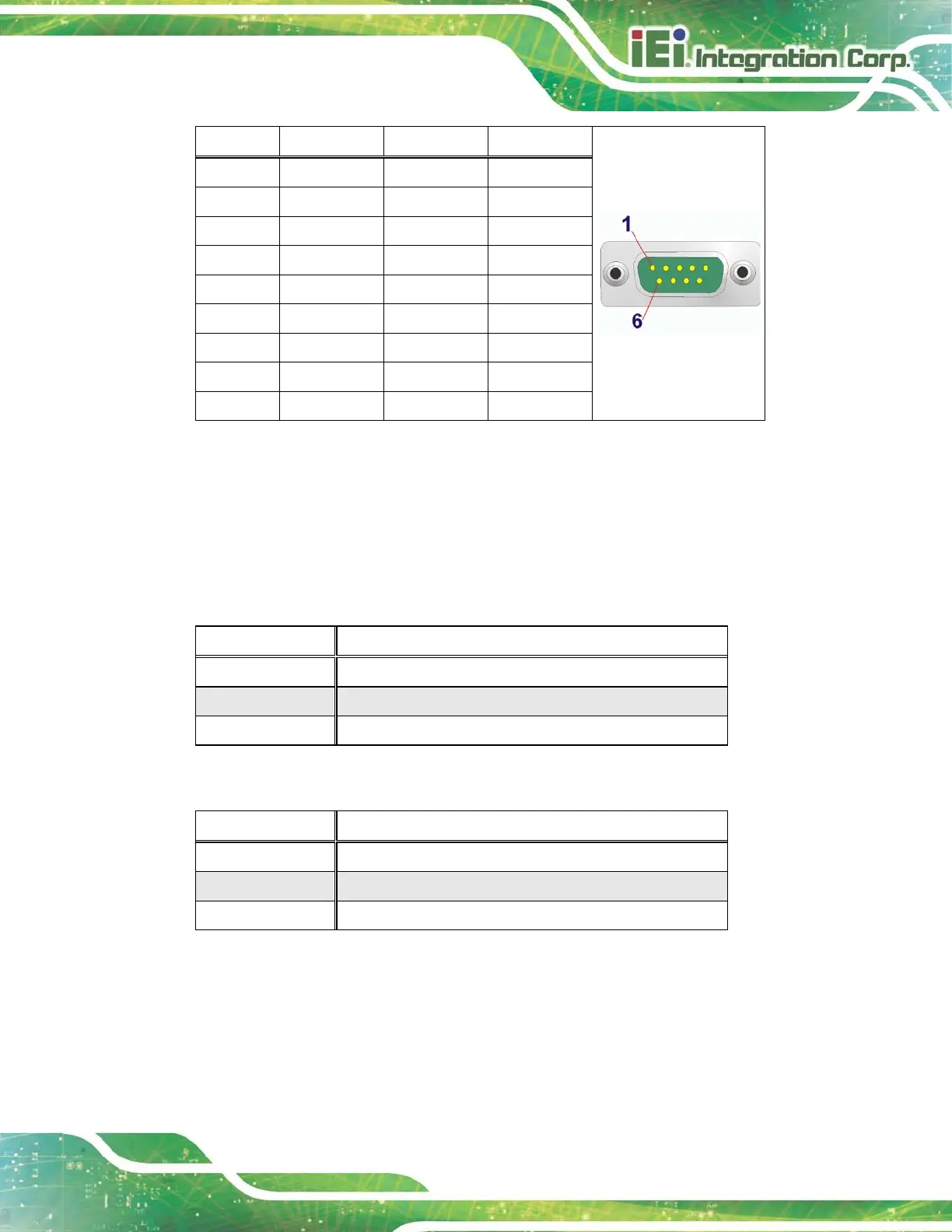
PIN NO. RS-232 RS-422 RS-485
1 DCD TXD422- TXD485-
2 SIN TXD422+ TXD485+
3 SOUT RXD422+ --
4 DTR RXD422- --
5 GND -- --
6 DSR -- --
7 RTS -- --
8 CTS -- --
9 RI -- --
Table 3-5: RS-232/422/485 DB-9 Serial Port (COM1) Pinouts
3.7.4 DB-9 Serial Port Pin 9 Selection
Pin 9 on the COM1 and COM2 DB-9 connectors can be set as the ring (RI) signal, +5 V or
+12 V. The jumper selection options are shown in Table 3-6 and Table 3-7.
JP1 Description
Short 1-2 COM2 RI Pin use +5 V
Short 3-4 COM2 RI Pin use RI (Default)
Short 5-6 COM2 RI Pin use +12 V
Table 3-6: COM1 Pin 9 Setting Jumper Settings (JP1)
JP2 Description
Short 1-2 COM1 RI Pin use +5 V
Short 3-4 COM1 RI Pin use RI (Default)
Short 5-6 COM1 RI Pin use +12 V
Table 3-7: COM2 Pin 9 Setting Jumper Settings (JP2)
The DB-9 Serial Port Pin 9 Setting jumper locations are shown in Figure 3-13 below.
 Loading...