NOTE:
When purchasing the arm please ensure that it is VESA compliant and that
the arm has a 100 mm
interface pad. If the mounting arm is not VESA
compliant it cannot be used to support the AFL3-W19A-AL flat bezel panel
PC.
Step 2: Once the mounting arm has been firmly attached to the surface, lift the flat bezel
panel PC onto the interface pad of the mounting arm.
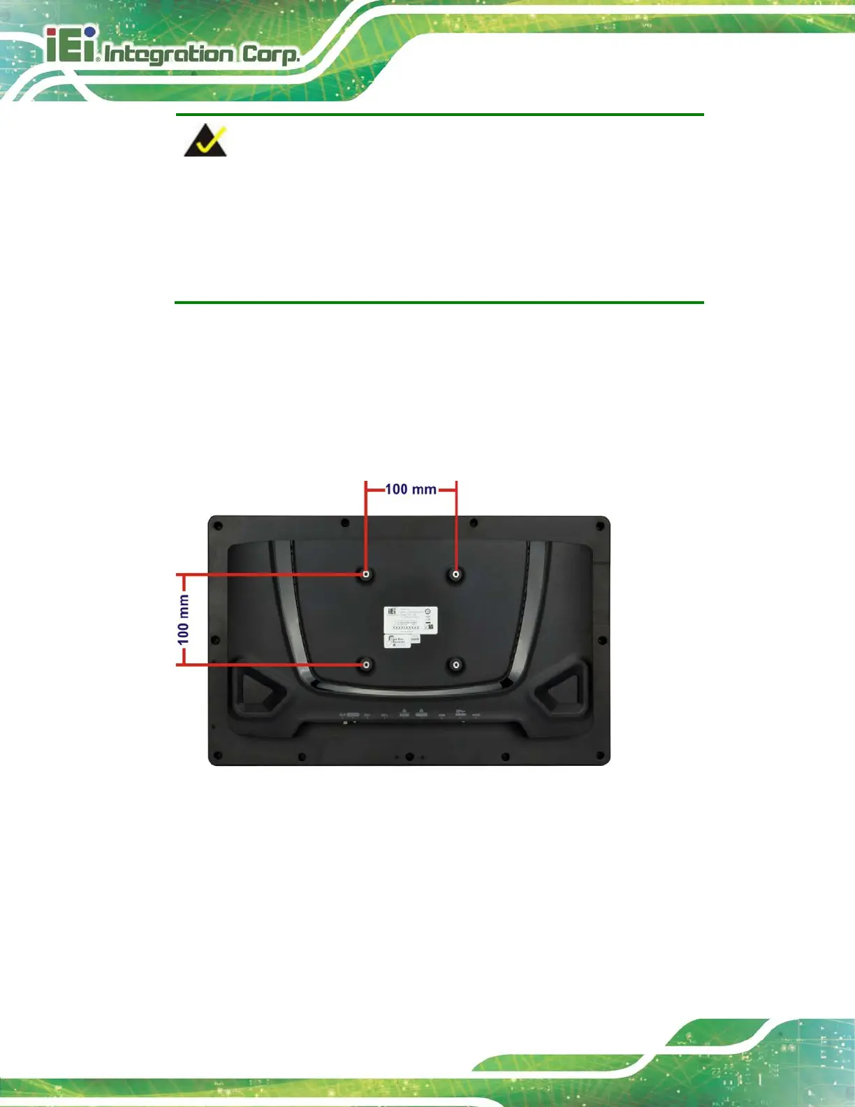
Step 3: Align the retention screw holes on the mounting arm interface with those in the
flat bezel panel PC (Figure 3-21).
Figure 3-21: Arm Mounting Retention Screw Holes
Step 4: Secure the AFL3-W19A-AL to the interface pad by inserting four retention
screws through the mounting arm interface pad and into the AFL3-W19A-AL.Step 0:

 Loading...