Power Connector Termination
Bring the 4 Pin Power Connector provided from the components box. To attach the supplied power connector to
the end of your power cable, follow the steps below. The female connector mates with the male connector in the
antenna.
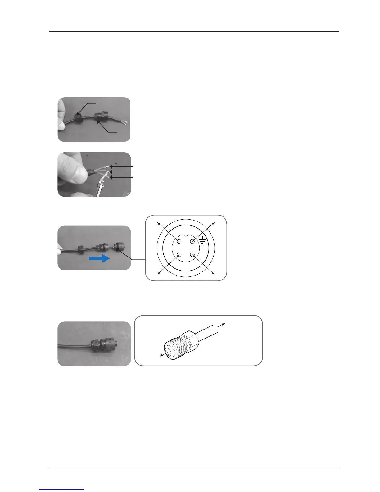
1. Pass the end of the power cable through the connector’s nut and housing as below.
Nut
Housing
2. Strip the jacket from the end of the power cable 22mm. Then strip back the insulation of all three wires 8mm.
Frame Ground / Green (or Yellow)
LIVE / Brown (or Red)
Neutral / Blue (or Black)
3. Connect the wires to the connector as below. Insert the wires to the supplied power connector by using a
at-head screwdriver. Refer to the pin-diagram below.
Connector
4. Slide the housing over the connector and tighten the nut onto the end of the housing. Conrm the completed
power connector as below. Connect one end of the cable to the radome bottom and the other end to the
ship's power.
 Loading...