Intermec EasyCoder 501 E – Installation & Operation Ed. 1 139
Appendix 4 Interfaces
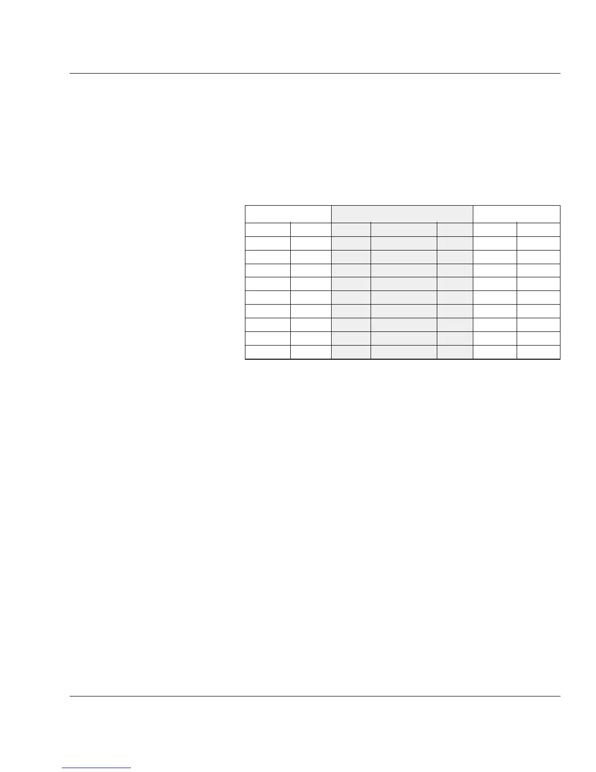
This diagram shows the confi guration of RS-232 cables between an
EasyCoder 501 and a computer with either a DB-9pin or DB-25pin
communication port. The cable should have a female DB-25pin
connector at the printer side.
1
/. If the communication cable is not confi gured to transmit any CTS signal to the
printer, a permanent CTS signal will automatically be produced.
2
/. Requires a strap fi tted on P-203, see previous page.
Host EasyCoder 501 Host
Signal DB-9 DB-25 Signal DB-25 DB-25 Signal
housing housing housing
1 shield 1 1 shield
RXD 2 2 TXD 2 3 RXD
TXD 3 3 RXD 3 2 TXD
CTS
1
8 4 RTS 4 5 CTS
1
RTS 7 5 CTS 5 4 RTS
GND 5 7 Signal GND 7 7 GND
16 + 5V
2
16
DSR 6 20 DTR 20 6 DSR
Standard Interface "uart1:", cont.
RS-232, cont.