Intermec EasyCoder 501 E – Installation & Operation Ed. 1148
Appendix 4 Interfaces
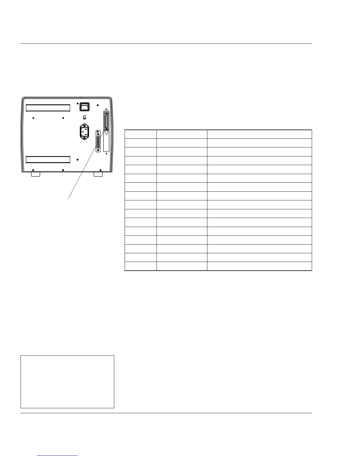
Pin Signal Name Remarks
1 /STROBE
2–9 DATA 0–7
10 ACK
11 BUSY
12 PE
13 SELECT
14–15 Not connected
16–17 GND
18 +5 VDC Ext Max. 200 mA. Enabled by strap on P-2
19 –30 GND
31 /INPRM
32 /ERROR
33-35 Not connected
36 /SLCTIN
37–38 GND Housing
Refer to the installation instructions for the Parallel Interface Board
for further information.
Parallel Interface
Board (option)
The EasyCoder 501 E can optionally be fi tted with a parallel interface
board. The parallel port is addressed in Intermec Fingerprint
as device "centronics:". Select "centronics:" as the standard IN
port using the instruction SETSTDIO (by default, "uart1:" is std
IN port)
1
.
Interface Cable Connectors
Computer end: Depends on type of host computer.
Printer end: 36-pin IEEE 1284B Centronics socket
"centronics:"
1
/. Intermec Shell either auto-
matically sets the correct stan-
dard IN and OUT port when
an application is selected or
prompts you to select one, see
Chapter 9.
230V
0