20
3.4 Scanner Water Cooling Specifications
The following sections outline water-cooling specifications for Mid-Power (Bayonet Input version) and
High-Power scanners.
3.4.1 Temperature, Humidity, and Water Cooling Specifications
Table 3-4 details temperature, humidity, and water-cooling specifications for both the Mid-Power
(Bayonet Input version) and High-Power Scanners.
Table 3-4 Temperature, Humidity, and Water Cooling Specifications
Water Cooling Requirement
Power levels greater than .5kW
Power levels greater than 1kW
Power levels greater than 1kW
Operating Temperature Range (⁰C)
Water Cooling Specifications
DI or Tap Water Temperature (⁰C)
Flow Rate Minimum (l/min)
6mm OD x 4mm ID Tubing or 1/4in Equivalent
3.4.2 Water Connection Overview
In order to best achieve the minimum flow rates, it is recommended to make all water-cooling
connections in-series. The following sequence outlines the typical water cooling connection to the head.
1. Water inlet to the fiber
2. Water outlet from the fiber
3. Water inlet to the collimator
4. Water outlet from the collimator
5. Water inlet to the scanner body
6. Water outlet from the scanner body and return to the laser or chiller
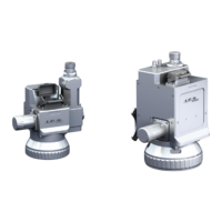
Figure 3-1 outlines a typical in-series water connection to the scanner. Although a 2D High-Power
scanner is pictured, the same principle applies to the Mid-Power scanner (Water Cooling Supply Fiber
Collimator Water Cooling Return). Please note that water flow is not limited to a specific direction
through the fiber, collimator, or scanner body.