80
10.3 Standalone Scanning System (No External Interface)
Although this is not as frequently encountered as Point and Shoot processing, a standalone scanning
system is sometimes desired. One such application that users may want a standalone system is for
research and development. With this type of setup, the user is limited to running the scanner though a
computer. Because the scanners have a large processing window, sometimes motion is not required.
Such a system allows users to quickly and effectively perform process development while keeping the
system relatively simple.
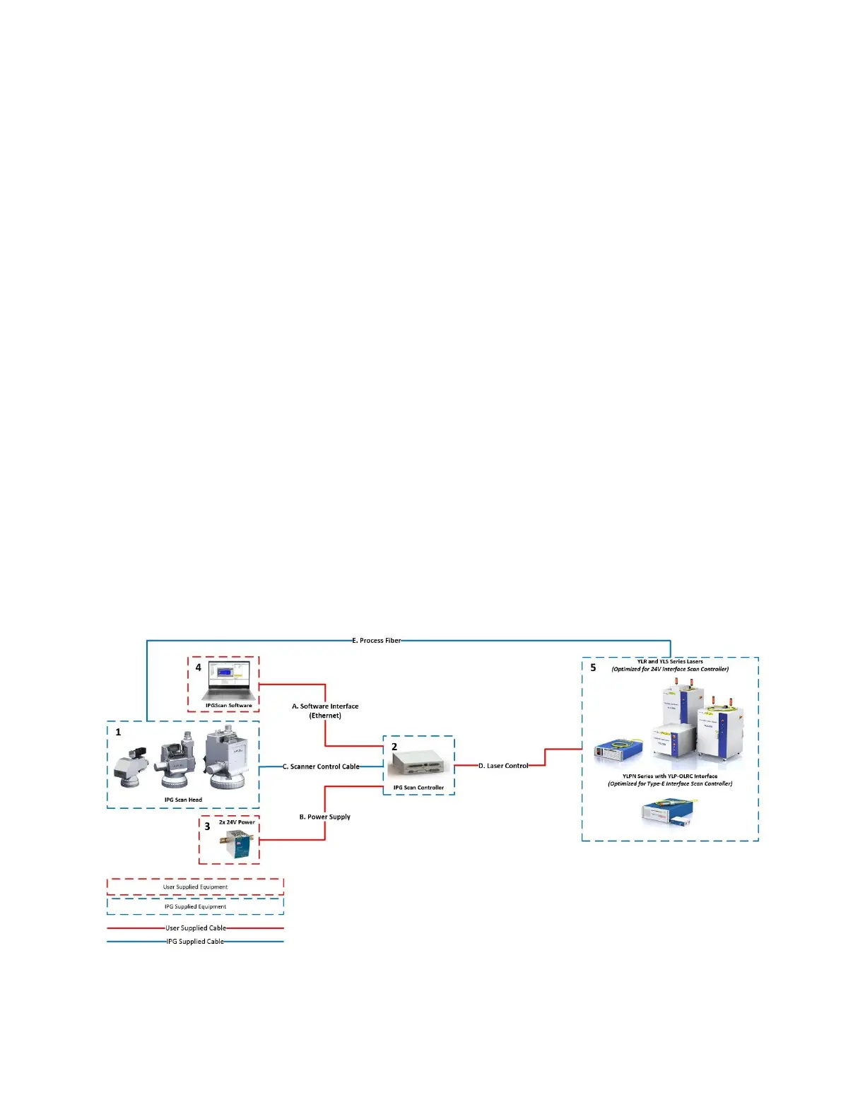
10.3.1 Standalone Scanning System Example
10.3.1.1 Standalone Scanning System Example
Equipment:
1. Scanner
2. Scan Controller
3. 24V Power Supplies
4. Computer
5. Laser
Cables
A. Computer to Scan Controller
B. 24V Power Supplies to Scan Controller
Should not exceed 15ft with 16 AWG
C. Scan Controller to Scanner
3m, 5m, or 10m Options Available
D. Scan Controller to Laser
E. Process Fiber
Figure 10-1 Standalone Scanning System Example Diagram