66
7.4 YLPN Series Lasers
The following sections outline the setup between a YLPN Series laser and an IPG Scan Controller.
In order to achieve optimal synchronization between a pulsed laser and scanner, the following
equipment should be utilized.
YLP-OLRC Interface
o This laser control box provides the interface connection (Parallel I/O) that allows the
Scan Controller to drive the laser.
o Refer to the lasers manual for additional detail.
Scan Controller with Type E Laser Interface
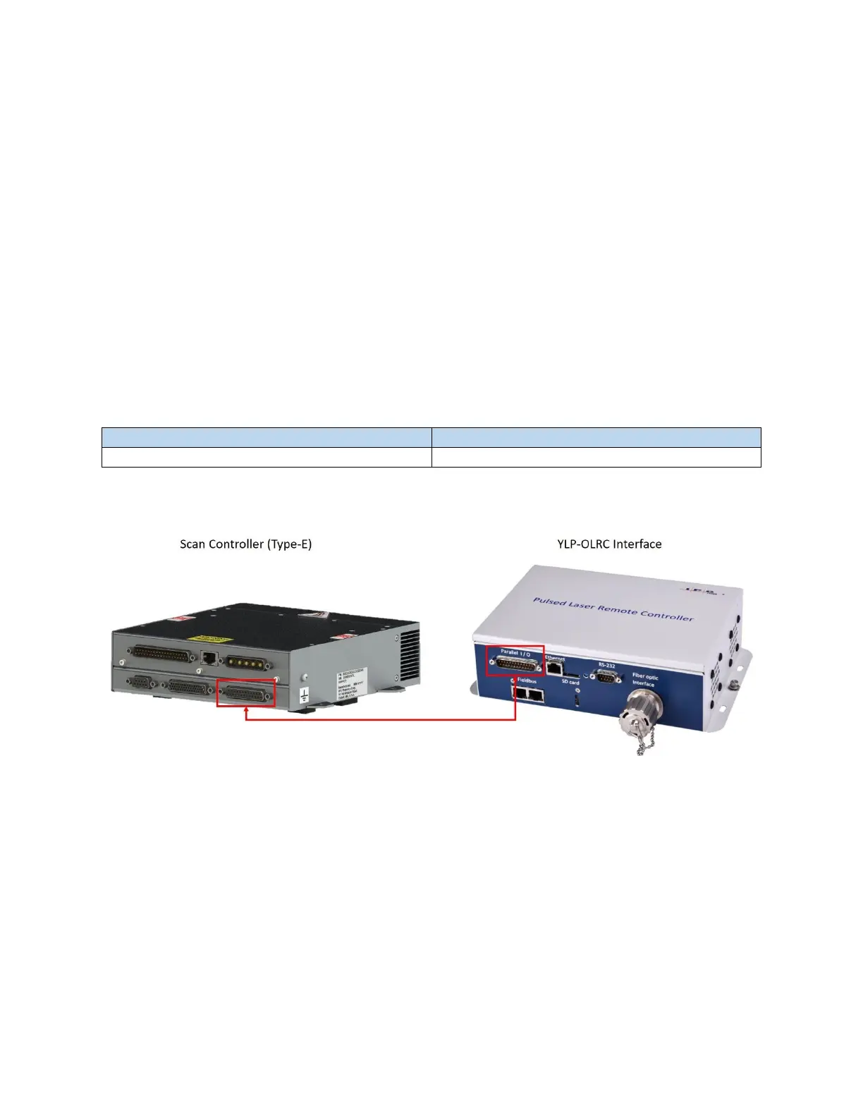
7.4.1 Scan Controller to YLPN Series Laser Connections
The following table (Table 7-1) outlines the Scan Controller laser connector and the YLPN (YLP-OLRC)
connector. The connection is a 1-to-1 DB 25 Male/Female. See Figure 7-5 which details the connection.
Table 7-1 Scan Controller (Type-E Laser Interface) and YLP-OLRC Connectors
Figure 7-5 Scan Controller to YLP-OLRC Interface Connection
7.4.2 YLPN Laser Source Setup
In order for the scanner to properly control the laser, the following settings should be configured in the
laser software.
1. Laser Options – The following should be enabled.
a. YLP-OLRC interfaces
b. Extended PRR
c. Sweep PRR
d. ACON
e. Auto latch power