48
6.1.1 Power Supply
The Scan Controller must be supplied with DC power in order to operate. Power is supplied to the
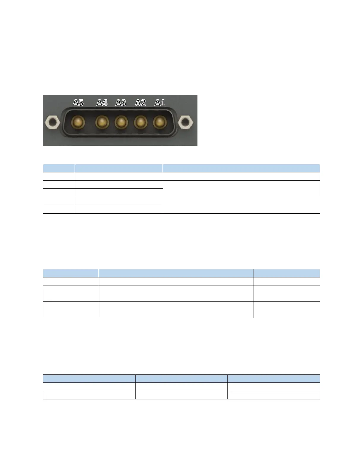
controller through a DB 5W5 connector located on the posterior side of the Scan Controller.
6.1.1.1 Power Pinouts
Figure 6-3 Male DB 5W5 Connector
Table 6-2 IPG Scan Controller DB 5W5 Pinout
Not used. Do not connect this pin to ground.
Power for electronics/communications (House Keeping)
24V Return (House Keeping)
GALVO POWER MUST BE ISOLATED. DO NOT CONNECT GALVO POWER SUPPLY
RETURN TO EARTH GROUND OR TO HOUSE KEEPING RETURN.
Table 6-3 Example Mating Connector Components - Power
D-Sub Contact Female Socket Gold 12 AWG Solder Cup
Receptacle for Female Contacts Housing D-Sub, Combo
Connector 5
25 Position Two Piece Backshell Connector Silver 180˚
Shielded
6.1.1.2 Power Requirements
IPG recommends the use of two separate power supplies for providing power to the Scan Controller.
Table 6-4 outlines the power requirements of the Scan Controller.
Table 6-4 IPG Scan Controller Power Requirements
Be mindful of voltage drop as the length of power supply cables increases.