56
6.2.1 Power Supply
The power connector is a DB 5W5, located on the Scan Controller and it is supplied with the scanner.
POWER SUPPLY MUST HAVE A TRANSIENT RESPONSE TIME OF AT LEAST 2ms FOR A
50% LOAD CHANGE.
DO NOT CONNECT POWER SUPPLY RETURN TO EARTH GROUND.
6.2.1.1 Power Pinouts
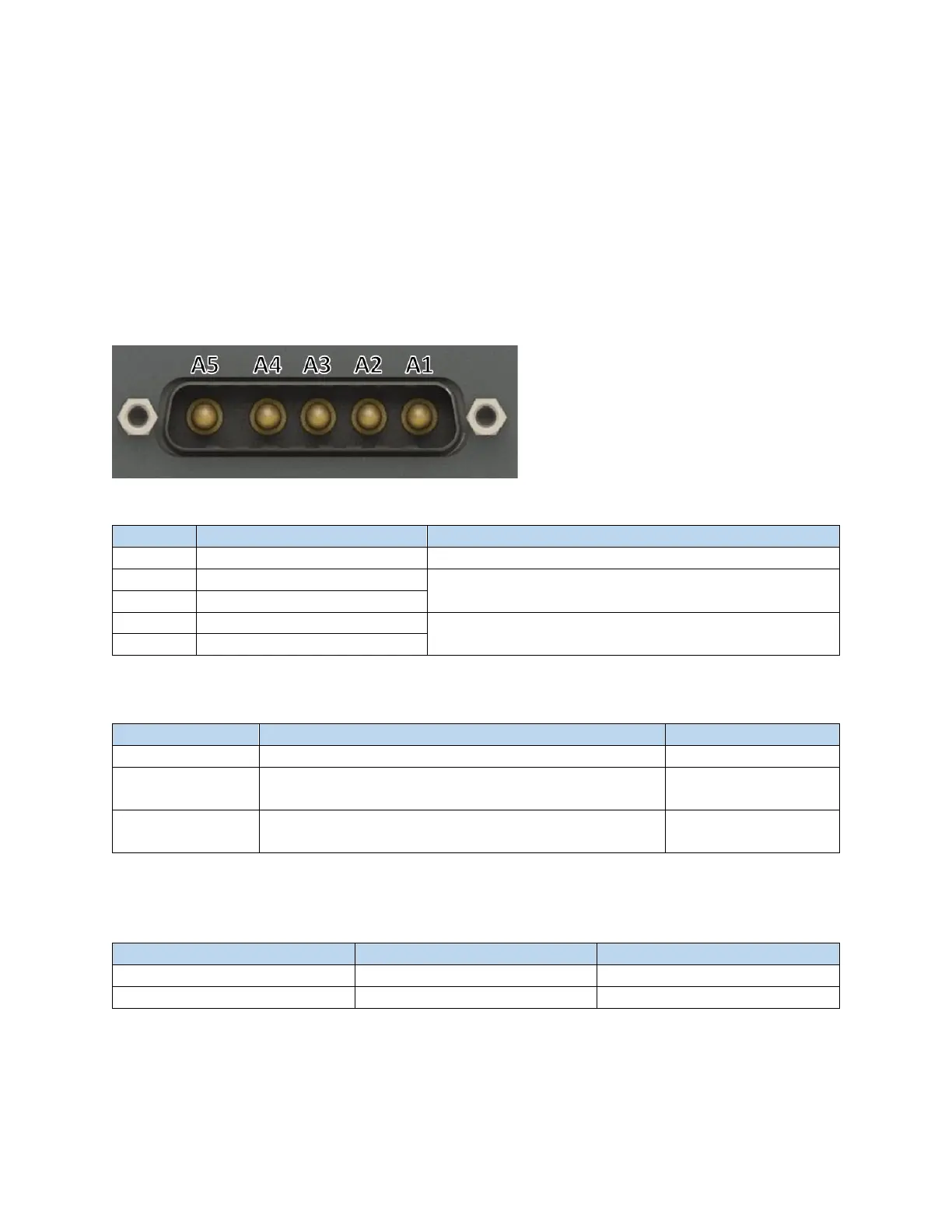
Figure 6-14 Male DB5W5 Connector
Table 6-11 XY2-100 DB 5W5 Pinout
Not used. Do not connect this pin to ground.
Power for electronics/communications (House Keeping)
24V Return (House Keeping)
Table 6-12 Example Mating Connector Components (XY2-100 Power)
D-Sub Contact Female Socket Gold 12 AWG Solder Cup
Receptacle for Female Contacts Housing D-Sub, Combo
Connector 5
25 Position Two Piece Backshell Connector Silver 180˚
Shielded
6.2.1.2 Power Requirements
Table 6-13 XY2-100 Power Requirements
Power for the scanner should be provided using the DB 5W5 connector. Do not
supply power to the scanner using the XY2-100 Digital In/Out Pinouts connector.
 Loading...