51
6.1.2 Ethernet
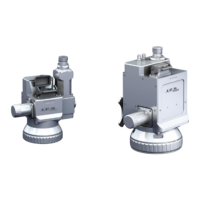
The Ethernet port is used for all communication between the Scan Controller and the host PC running
IPGScan. Users have no access to the protocol data going through this line.
Figure 6-7 RJ45 Ethernet Connector
The PC’s Ethernet adapter should be initially configured for DHCP, however a static IP can also be used.
IPG recommends a direct connection between the Scan Controller and PC, capable of 100 Mbits/sec.
Table 6-5 - Recommended Ethernet Cable Specifications
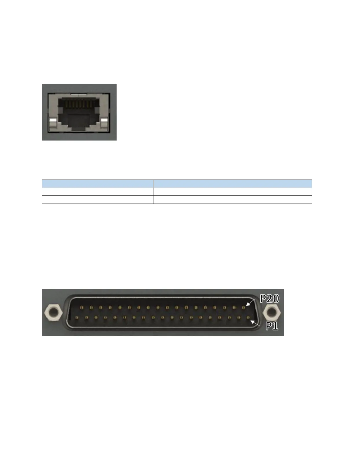
6.1.3 External Interface
The External Interface connector (User I/O) is for external control of the Scan Controller through means
of digital communication with devices such as PLCs, robots, or encoders/motors. This interface provides
users with a means to trigger when the scanner should start processing as well as a number of other
functions related to automating the system.
Figure 6-8 Male DB 37 Connector
I/O signals out of this connector are either 3.3VTTL or RS422 compatible. Bidirectional I/O signals are not
isolated and IPG does not recommend direct connection with them. To properly integrate the Scan
Controller into an automated system, an External Interface Device such as the 24V Interface, Extended
IO Interface, or Motion Interface should be utilized. Please refer to the External Interface Board User
Guide (DOCOXUGSCNXX0002) for additional details.