33
4.4 Fiber Connection
4.4.1 Overview
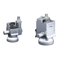
The scan heads use IPG Process collimators that are factory aligned and water-cooled for optical &
thermal stability. Collimators are equipped with FCH-8/HLC-8, HLC-16 (sometimes referred to as QBH),
or LCA/QD type fiber receivers which are only compatible with the corresponding fiber bayonets.
4.4.2 Fiber Installation (HLC and LCA Receivers)
The procedure for fiber installation entails the following:
1. Power off the scan head/Scan Controller.
2. Rotate the head so the collimator is angled down towards the ground.
a. This is to help prevent debris from entering into the collimator.
3. Release the debris tray.
a. Refer to section 4.4.3.1 for information concerning debris tray operation.
4. Perform a fiber inspection.
a. Please refer to the lasers manual for specific information pertaining to fiber inspection
and cleaning.
5. Insert the fiber into the fiber receiver.
a. Refer to sections 4.4.3.2 or 4.4.3.3 for details concerning specific fiber receiver
operation.
6. Connect water lines (if power levels require the use of water-cooling).
a. Prior to rotating the head vertical, users should turn on the chiller and inspect water
lines for any leaks.
7. Retract the debris tray.
8. The scanner can now be powered up and rotated into any desired position for use.
4.4.3 Fiber Removal (HLC and LCA Receivers)
The procedure for fiber removal entails the following:
1. Power off the scan head/Scan Controller.
2. Rotate the head so the collimator is angled down towards the ground.
a. This is to help prevent debris from entering into the collimator.
3. Release the debris tray.
a. Refer to section 4.4.3.1 for information concerning debris tray operation.
4. Disconnect water lines (if power levels require the use of water-cooling).