EasyManua.ls Logo

IPG Photonics Scanner Series - XY2-100 Digital Signals

IPG Photonics Scanner Series
109 pages
Print Icon
To Next Page IconTo Next Page
To Previous Page IconTo Previous Page
Loading...
59
6.2.2 XY2-100 Digital Signals
The following entails digital inputs and outputs for the XY2-100 signals from an external controller.
Please see the XY2-100 specification for electrical specifications on these signals. For Mid-Power Scanner
with XY2-100 Interface applications, the user is responsible for configuring communications to the
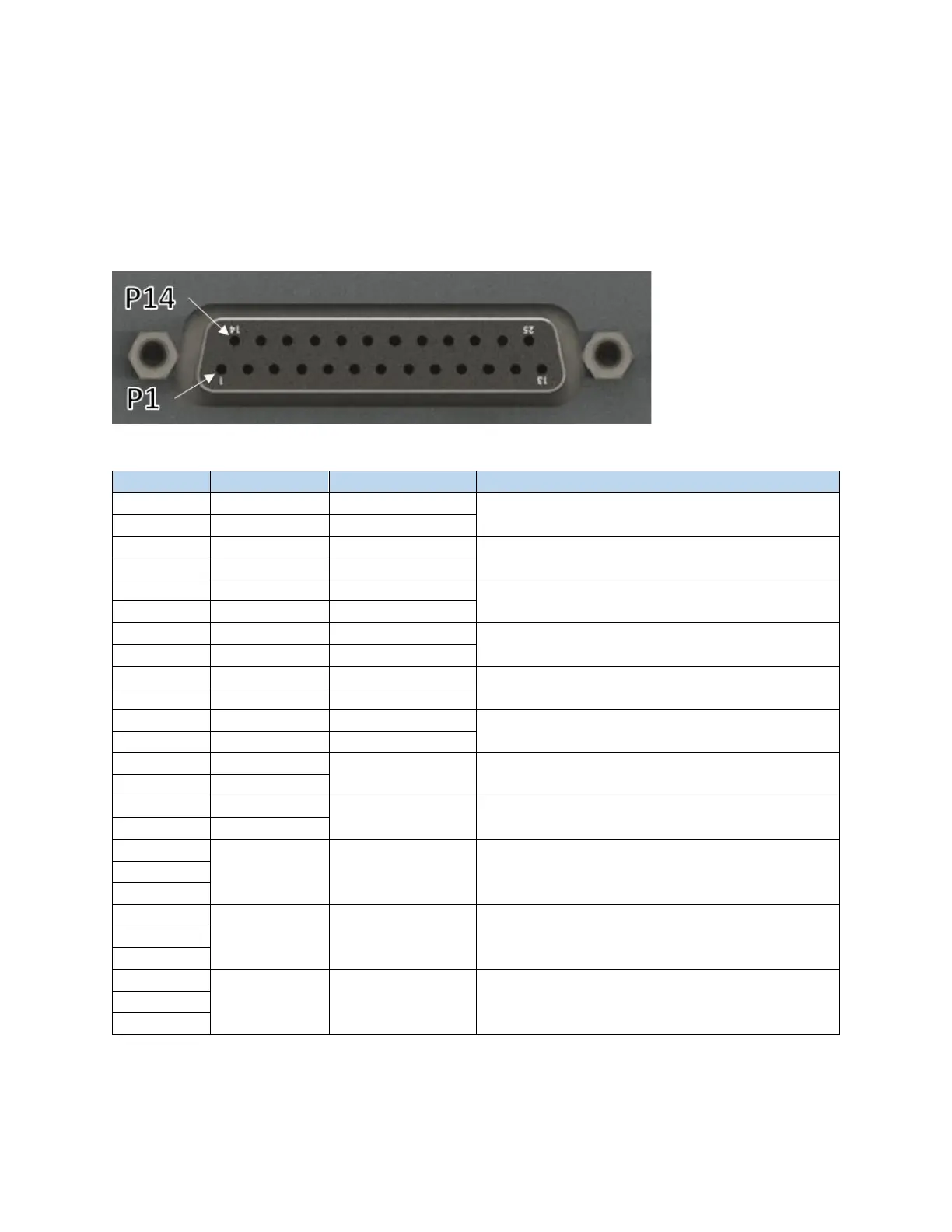
scanner. Scanner control and status should be communicated through this DB 25 female connector.
Figure 6-18 Female DB 25 Connector (XY2-100)
Table 6-14 XY2-100 Digital Signal Pinouts
Pin
Name
Direction
Description
1
CK-
Input
2Mhz Clock
14
CK+
Input
2
SYNC-
Input
Sync Signal
15
SYNC+
Input
3
XD-
Input
X Channel Data
16
XD+
Input
4
YD-
Input
Y Channel Data
17
YD+
Input
5
ZD-
Input
Z Channel Data (If Z axis is present)
18
ZD+
Input
6
STAT-
Output
XY2-100 Status Word
19
STAT+
Output
7
NC
-
Do not connect
20
NC
8
NC
-
Do not connect
21
NC
9
+V Servo
PWR
Do not connect
22
10
23
GND
PWR
Do not connect
11
24
12
-V Servo
PWR
Do not connect
25
13

Table of Contents

Related product manuals