53
6.1.6 Laser Control
This connection allows communication with the laser. This connector can be either a DB 15 or a DB 25
pin connector depending on the laser to be controlled.
The DB 15 version has an analog power control signal and is used with YLS and YLR laser types. Refer to
Table 6-7 for the corresponding DB 15 pinouts. The DB 25 version has digital power control signals and is
used with YLPN lasers with a Type E interface. Refer to Table 6-9 for DB 25 connector pinouts.
Actual wiring between Scan Controller and laser source is shown in Section 7.
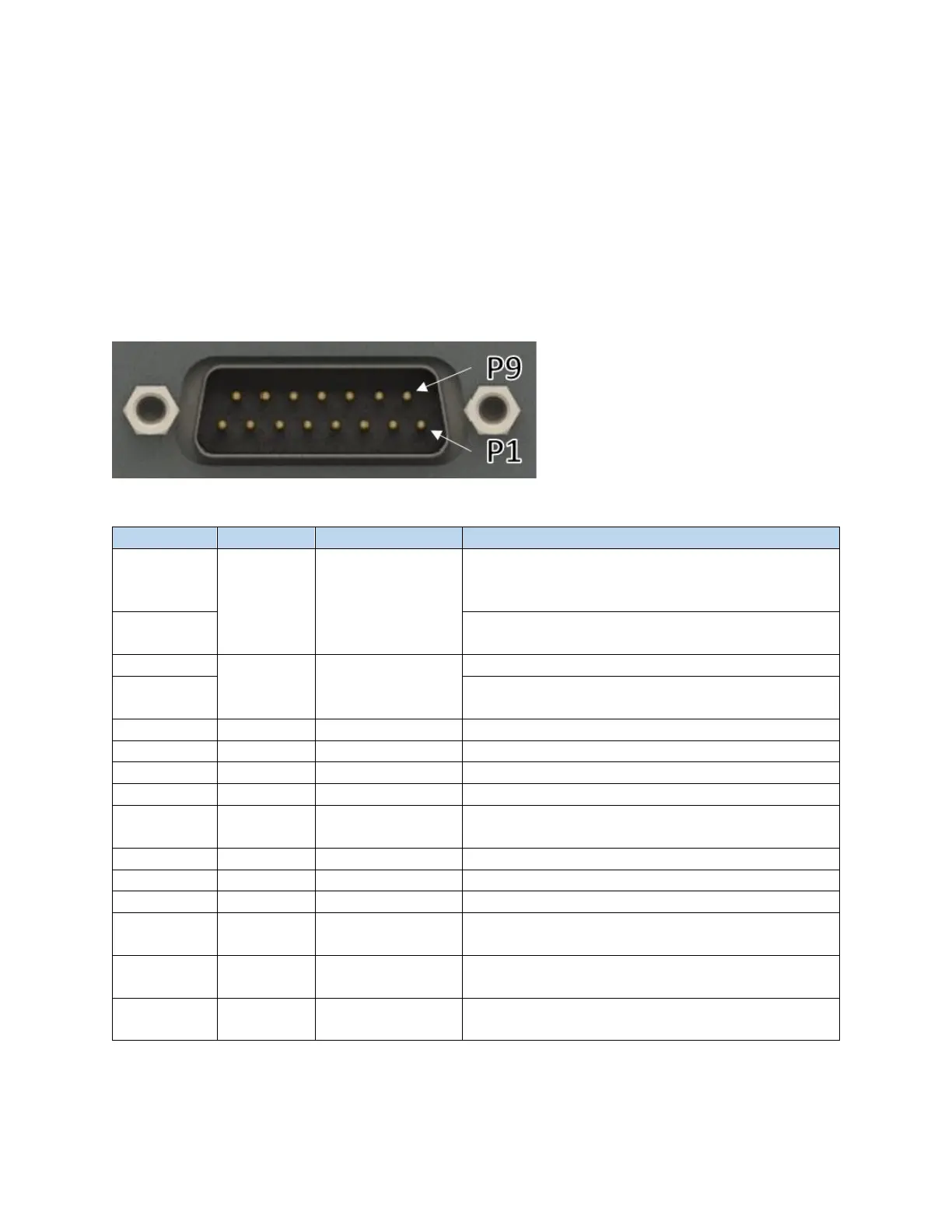
Figure 6-11 Male DB 15 Connector (24V Laser Interface Connector)
Table 6-7 DB 15 Pinout
Analog Control +
For use with non-AMB lasers
Core power control on AMB lasers
Analog Control Return
Pins 9, 10, 5, and 7 are all common
Modulation Return
Pins 9, 10, 5, and 7 are all common
Program Start/Emission Enable
Common Return
Pins 9, 10, 5, and 7 are all common
Common Return
Pins 9, 10, 5, and 7 are all common
Analog Control + (AMB Ring Control)
Do not use on non-AMB lasers
Air Pressure Present
Contact closure to GND when air pressure present