54
Table 6-8 Example Mating Connectors – DB 15 Laser Control
DB 15 Connector
Assembly - Solder
D-Sub Straight Connector, Solder, Shielded Socket,
DB15, Female, for 30-20 Wire Gauge
DB 15 Connector
Assembly – Crimp
D-Sub Straight Connector, Crimp-On, Shielded Socket,
DB15, Female, for 28-24 Wire Gauge
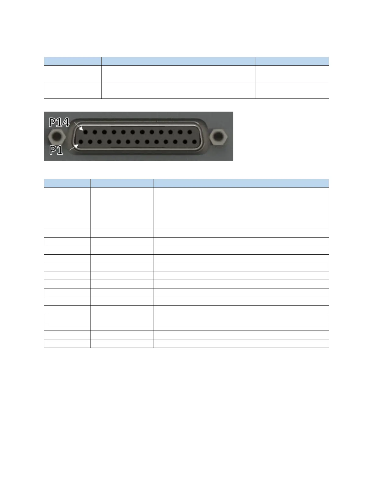
Figure 6-12 Female DB 25 Connector (Type-E Laser Interface Connector)
Table 6-9 DB 25 Pinout
8-bit bus, range 0x00..0xFF (hex) or 0.255 (decimal).
Least significant bit (lsb) (D0) corresponds to Pin 1.
Most significant bit (msb) (D7) corresponds to pin 8.
00h (0): Minimum output power
FFh (255): Maximum output power
Latches power setting into the laser by the rising edge
5V for independent operation of guide laser
Turn on emission enable (EE) signal on laser
Turn on emission modulation (EM) signal on laser
Pulse Repetition Rate (Synchronization)
Guide laser (red diode) ON/OFF