61
7 Laser Connections and Configuration
7.1 Overview
The following diagrams outline the electrical interface/configuration for connecting a Scan Controller to
the specified IPG laser model.
This is not an all-inclusive list of required connections for setting up the laser.
Users should refer to their lasers manual for pin-outs, safety connections, remote
key switch connections, and sequencing diagrams specific to the operation of the
laser.
7.2 YLR Series Lasers
The following sections outline the setup between a YLR Series laser and an IPG Scan Controller.
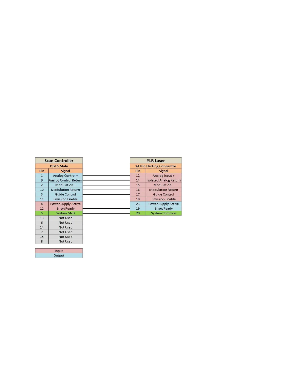
7.2.1 Scan Controller to YLR Series Laser Connections
Please refer to Figure 7-1 for Scan Controller to YLR Series laser connections.
Figure 7-1 Scan Controller to YLR Laser Connections
7.2.2 YLR Laser Source Setup
Prior to processing, YLR Series lasers must be setup for the desired mode of processing. The following
procedures outline the steps for setting up a YLR-Series laser in QCW mode or CW mode.
For more specific details on laser operation, please refer to the manual provided with the laser.
CW Mode
1. Turn the key switch on the laser to ON.
2. Using the touch screen, set the laser to CW.
3. Enter the Setup menu and set the following parameters as detailed.
a. Gate: Disabled
b. Ext. Emission Control: ON