Эксплуатация – АВТОМАТИЧЕСКИЙ РЕЖИМ
OPTIMA FULL DIAGNOSTIC
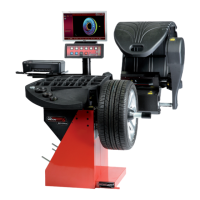
Operation - AUTOMATIC
"OPTIMA FULL DIAGNOSTIC"
7.11.1.2 Меню "3D PLOT"
"3D PLOT" (Рис. 7-84)
2 F2 (Рис. 7-41)
"ASSEMBLY INDICATION".
:
(Рис. 7-84) - :
F2 "TREAD PLOT".
F3 3D--
.
.
F4 .
F5
.
7.11.2 Возможности режима OPTIMA
FULL DIAGNOSTIC
•
6
•
7.10.1
,
, .
Optima
:
7.11.2.1 TREAD PLOT
F1, "Optima" (1, Рис. 7-85),
F2, "TREAD PLOT" (4, Рис. 7-85),
"TREAD PLOT" (Рис. 7-86),
(A)
.
Примечание:
(I) ,
(A)
.
.
(B)
(C)
.
(D),
.
Примечание:
.
ВНИМАНИЕ:
Рекомендации об износе покрышки
соответствуют общепризнанным нормам для
легковых автомобилей, оборудованных
покрышками серийного производства – другие
типы покрышек могут не соответствовать этим
рекомендациям.
7.11.1.2 Menu "3D PLOT"
The "3D PLOT" screen (Fig. 7-84) is accessed with Item
2 of the F2 Menu (Fig. 7-41) in the "ASSEMBLY
INDICATION" screen.
The screen displays a three dimensional graphic analysis
of the complete wheel.
The screen also contains the following Menu items:
(Fig. 7-84) - Menu:
F2 Go back to the "TREAD PLOT" screen.
F3 Move the 3D image to the right and the left, compared
to the horizontal. Press the left or right key.
F4 Zoom and reset graphic image.
F5 Chromatic sensitivity adjustment. Press the high or
low key.
7.11.2 "OPTIMA FULL DIAGNOSTIC"
Operation
• Lock the wheel
Chapter 6
• Perform the measuring run
Chapter 7.10.1
At the end of the run, if the RUNOUT limits are not
exceeded, the balancer displays the "Balancing" screen.
To display the results of the Optima diagnostic, start from
the basic screen and select the following:
7.11.2.1 TREAD PLOT
F1 Menu, Item "Optima" (1, Fig. 7-85),
F2 Menu , Item "TREAD PLOT" (4, Fig. 7-85),
The "TREAD PLOT" screen is displayed (Fig. 7-86). The
top displays the flat view of the tread (A), with the
various colours referring to the various depths.
Note:
The angular position index (I) is fixed, whilst the tread
display (A) moves when the operator turns the wheel
with his hand. The index corresponds to the 12
physical position on the wheel.
The graph on the bottom (B), reproduces the tread section.
Above this numeric indications in coloured boxes (C) indicate
the depth of the various zones along the whole width.
The values in the boxes and their colour, refer to the table
on the right (D). The table relates the tread wear limits to
the colours that are then displayed in the boxes, according
to the data reading.
Note:
The table limits cannot be changed by the operator.
WARNING:
Tire wear recommendations based on the generally
recognized standard for a passenger car equipped
with OEM Tires – Other Tire types and applications
may not match these recommendations exactly.