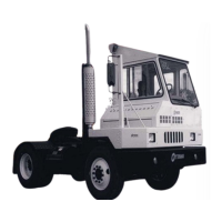
DCE80-100E
Technical Handbook
Engine Cummins QSB 5.9
Description
40
P.Group 30
TDCE01
04GB
Fuel system
The fuel circulates in two circuits - the high-pressure circuit and
the low-pressure circuit. When the engine is started, the feed
pump draws fuel from the tank and delivers it at relatively low
pressure through fine filters up to the injection pump. This then
delivers fuel at high pressure to the injection pump which sup-
plies the fuel in atomised form to the engine combustion cham-
bers.
Excess fuel which is circulated in the low-pressure system is also
cleaned in the fine filters and is returned through a spill valve
back to the tank.
The fuel system includes the following components:
Fuel tank - a separate unit located on the left-hand side of the
forklift. The fuel volume in the tank can be read on a gauge on the
instrument panel.
Feed pump - supplies fuel at a certain pressure and flow rate to
the injection pumps.
Spill valve - which restricts the fuel feed pressure and provides
continuous venting of the fuel system. The excessive fuel is flow-
ing through the injection pump before it is fed through the return
line to the fuel tank.
Fuel pre-filter - with drain valve for condensate
Injection pump and injectors