DCE80-100E
Technical Handbook
Main hydraulics
Description
11
P.Group 70
TDCE01
04GB
Lifting
The lifting cylinders are supplied from a separate section in the
main valve. The lifting speed is determined by the position of the
lift control lever. The flow of fluid from the hydraulic pumps can be
changed by altering the engine speed, which thus provides an
additional means of controlling the lifting speed.
During lowering, the fork carriage and the effect of the load force
the fluid from the lifting cylinders into the reservoir. A lowering
brake valve in the supply line to each lifting cylinder determines
the lowering speed and also limits the flow of fluid in the event of
hose failure. The lowering brake valves are of pressure-compen-
sated type and therefore permit only a certain predetermined
flow, thus ensuring a constant lowering speed, regardless of the
actual load.
Some of the return fluid is by-passed to the valve block and from
there to the cooling circuit of the driving brake.
The lifting cylinders are filled with fluid on the piston side to pre-
vent corrosion. This fluid is not pressurized and is fed back to the
reservoir in step with movement of the piston. Any leakage is also
drained to the reservoir through these lines.
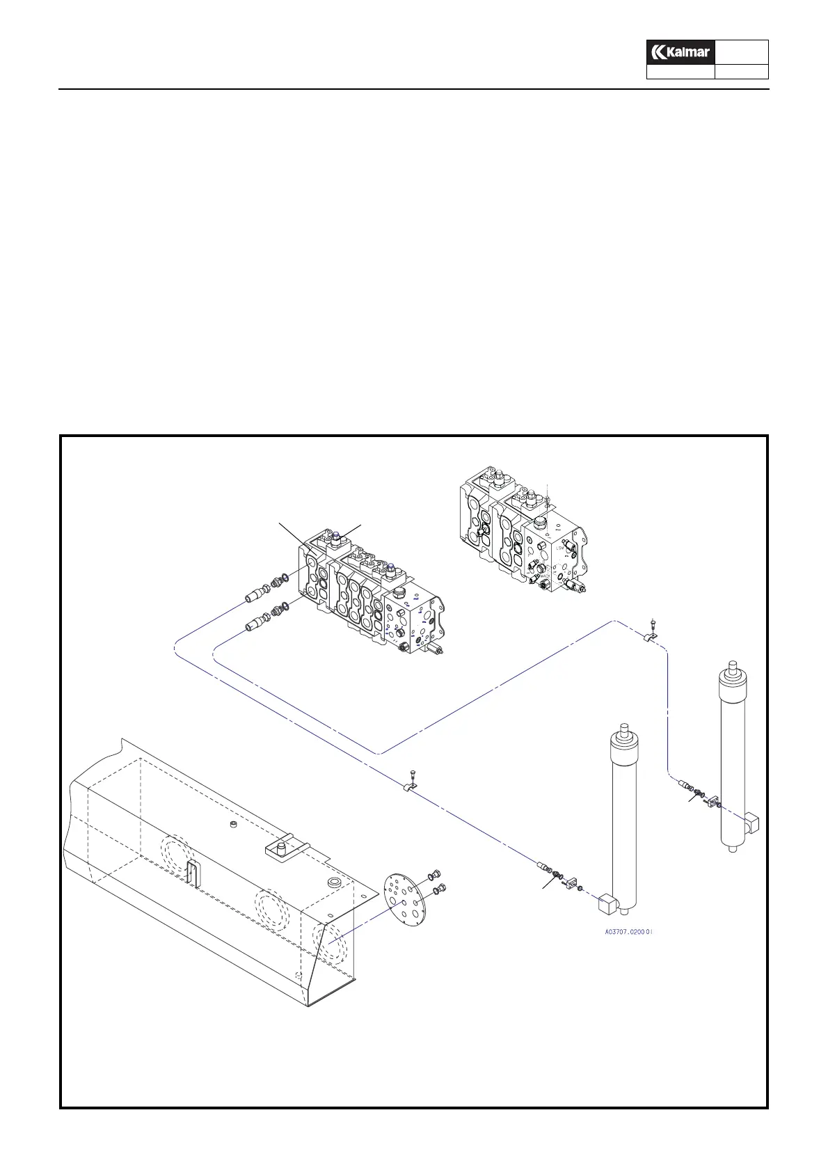
Lifting function
The numbers correspond to the hydraulic diagram
A = System with separate side-lift hydraulics
12. Main pressure limiting valve LIFT
16. Main valve, control section LIFT
26. Lift cylinder
27. Lowering brake valve
16 12
26
26
27
27
31
KL1834
A