DCE80-100E
Technical Handbook
Sidelift, hooks, type C
Service
31
P.Group 80
TDCE01
04GB
25x1,5mm²
Opt.
D
C
D
C
XB777
123
4
5
67 8
9
10
11
12
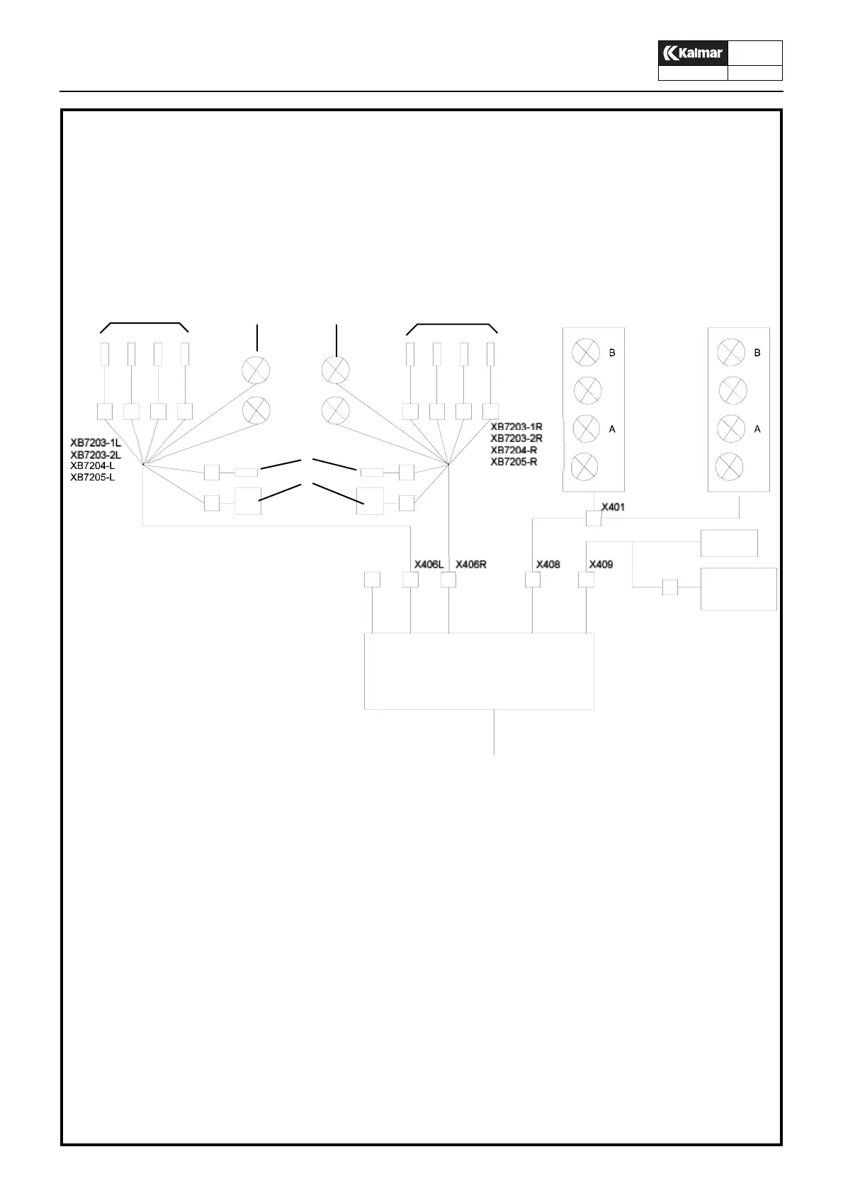
1. Sensor alignment, left side
2. Work light, left side
3. Work light right side
4. Sensor, stop at 30’ (optional)
5. Relys and valves, stop at 30’ (optional)
6. Sensor alignment, right side
7. Indikeringslampor left side, see separate description
8. Indikerinslampor right side, see separae description
9. Main valve sidelift
10. Sensor, interruption of lowering at bottom position (mechanical levelling)
11. Electrical central unit
12. From chassis
See also circuit diagram A45760.0100
1
5
2
4
6
7
8
3
Block diagram