DCE80-100E
Technical Handbook
Sidelift, hooks, type C
Service
26
P.Group 80
TDCE01
04GB
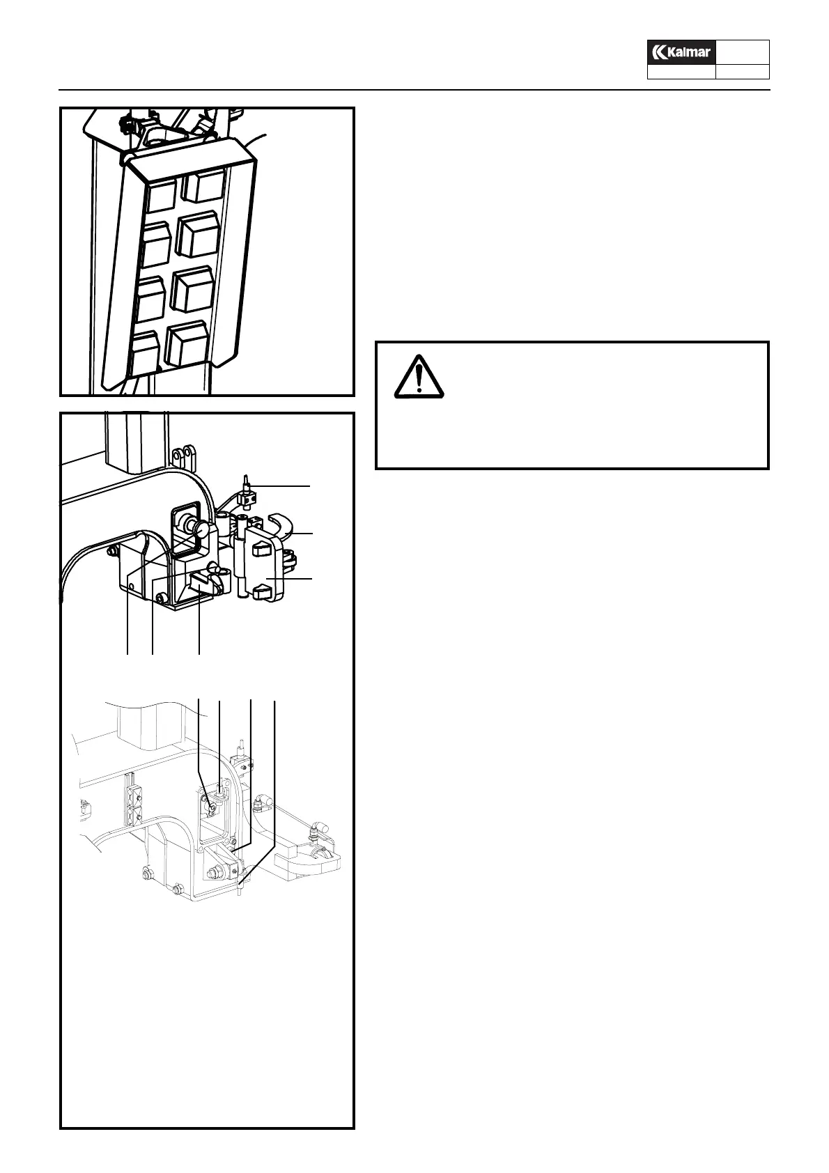
Indicating lamps on side-lift
1. Red lamp Left locking plate released
2. Red lamp Right locking plate released
3. Orange lamp Alignment Left, upper container
4. Orange lamp Alignment Right, upper container
5. Orange lamp Alignment Left, lower container
6. Orange lamp Alignment Right, lower container
7. Green lamp Left locking plate locked
8. Green lamp Right locking plate locked
Alignment control
A spring-loaded contact pin and an inductive sensor at each
twist-lock is used for control of alignment against one or two con-
tainers . The sidelift is fully aligned onto the container when the
contact pins on both sides have been depressed and the distance
between each pin and sensor is less than to 8 mm.
When lifting one container: When lamps 5 and 6 light up, the side
locking plates can be locked.
When lifting two containers: When lamps 3, 4, 5 and 6 light up,
the side locking plates can be locked.
N.B. It is possible to lock the side locking plates without in-
dication of alignment. Therefore, never lock before lamps 5
and 6 (one container) or 3, 4, 5 and 6 (two containers) light
up.
In the locked position for one or two containers, the red lamps 1
and 2 go out and at the same time the green lamps 6 and 7 light
up. During lift operation the lamps 3, 4, 7, 8 should always be
alight while 5 and 6 should be extinguished..
Checking of indicating lamps
1. Check that the contact pins are freely moveable in and out.
A pin which binds in the inner position may indicate correct
alignment although the sidelift is not in contact with the con-
tainer.
Lubricate the contact pins when needed.
2. Check that the indicating lamps 1 and 2 Red are alight when
the locking plates are released.
3. Check that the indicating lamps 3, 4, 5 and 6 Orange light up
at the alignment of two containers, alternatively 5 and 6 at
the alignment of one container..
4. Check that the lamps 7 and 8 Green light up when locking
the locking plates and that 1 and 2 Red go out.
5. The sensors 7 and 8, se illustration, for alignment should be
adjusted to give a signal when the contact pins are de-
pressed. See Control and adjustment of alignment
against container, page 28.
Indicating lamps
on the sidelift
1
2
3
4
5
6
7
8
WARNING!
Whenever the indicating lamps do not work properly, the
attachment should be taken out of service for repair. The
use of an attachment with faulty indication lamps could
be hazardous!
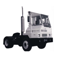
KL1792
KL1791
1. Lifting hook
2. Spring loaded contact pin , alignment
against lower container
3. Spring loaded contact pin , alignment
against upper container
4. Side locking plate
5. Sensor, locking plate locked/released
6. Activator for sensor
7. Sensor, alignment against lower container
8. Sensor, alignment against lower container
123
4
5
6
3 7 8
2