DCE80-100E
Technical Handbook
Accumulator
Description
32
P.Group 70
TDCE01
04GB
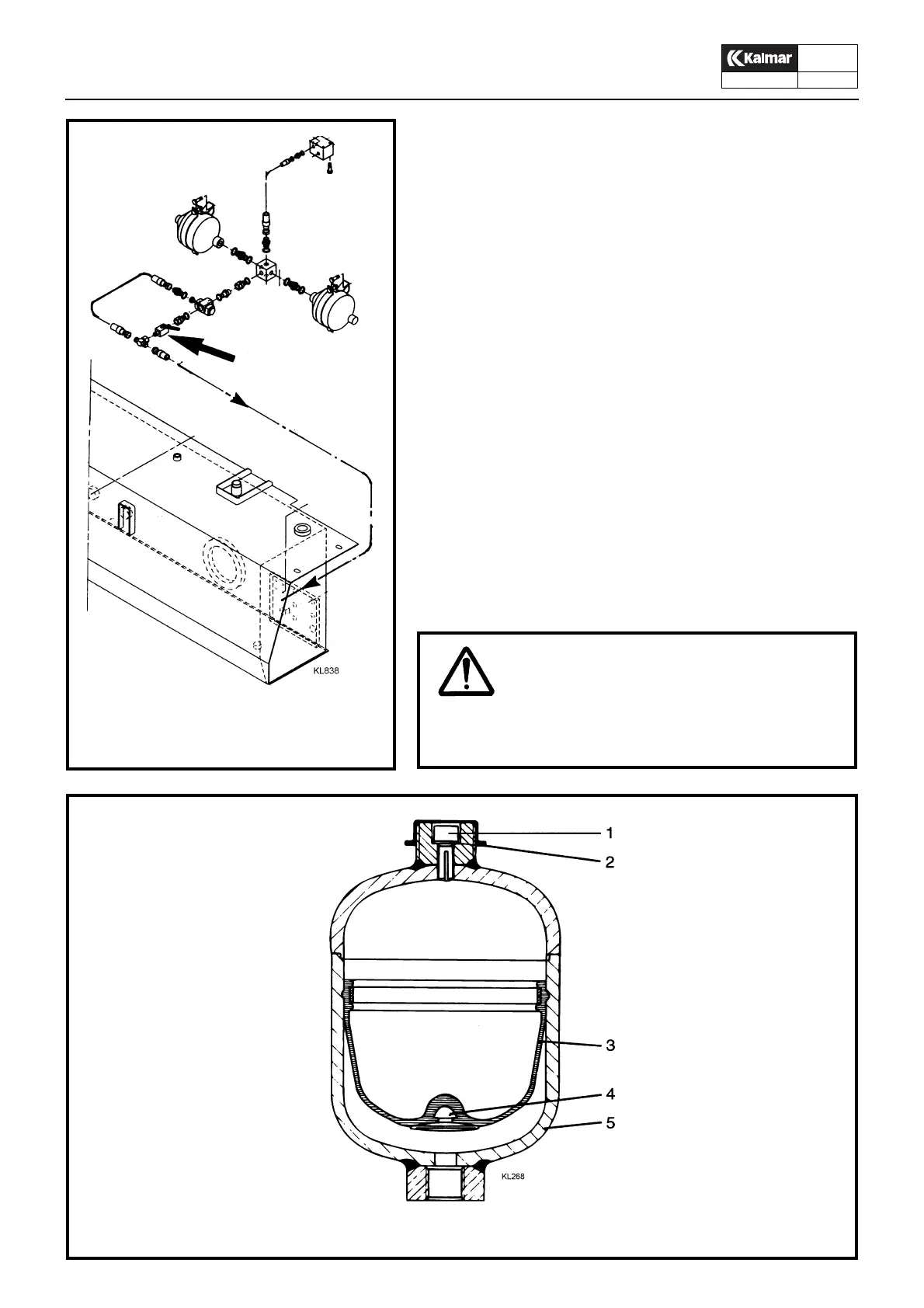
Accumulator
The hydraulic system is connected to membrane type accu-mu-
lators which are pre-charged with nitrogen at a pressure of
100
ba
r. The membrane is forced upward causing the pressure of the
nitrogen to increase as the accumulator becomes charged with
hydraulic fluid. When the hydraulic system requires power from
the accumulator, the membrane presses fluid back into the sys-
tem.
The accumulator is fitted at the top with a connection for testing
the pressure of the nitrogen, and for refilling nitrogen with the aid
of special filling equipment.
The pressurized fluid from the accumulator is utilized to power
the driving brake and parking brake systems, and to supply the
pressure reducing valve of the servo hydraulics.
An evacuating valve is fitted between the accumulator and reser-
voir. This valve shall be used to relieve the accumulator of pres-
sure before carrying out any work on the hydraulic system.
42. Accumulator evacuating valve
42
WARNING!
The hydraulic system includes high-pressure accumula-
tors. Open the accumulator evacuating valve to release
pressure before working on the hydraulic system.
Accumulator
1. Connection
2. Seal
3. Membrane
4. Safety plate
5. Steel bottle