DCE80-100E
Technical Handbook
SUPERVISION
Diagram explanations
11
P.Group 20
TDCE01
04GB
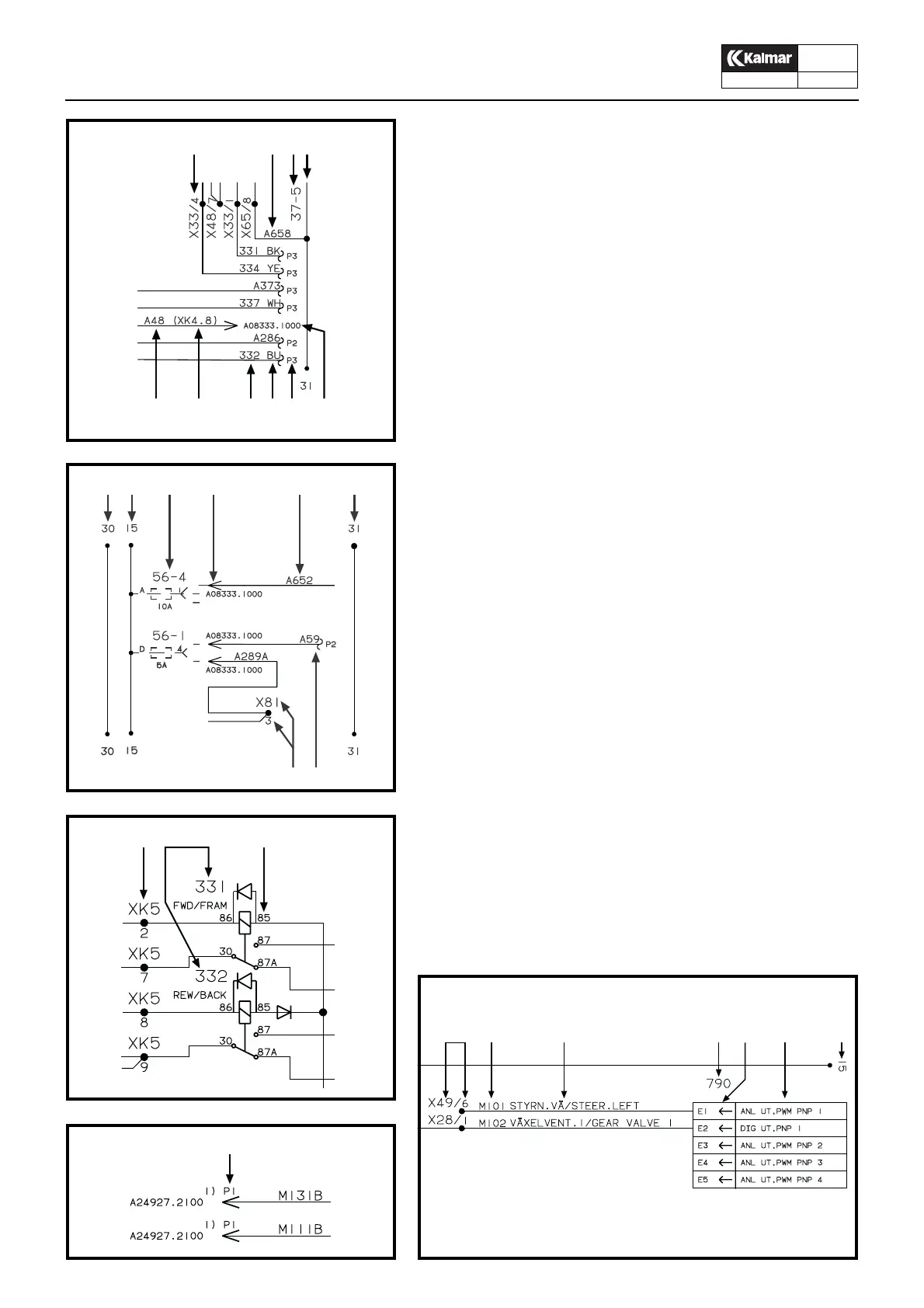
Electrical diagram explanations
A. Connector, located outside the central electrical unit circuit
board.
X = Connector
33 = Pin number
/4 = Pin number 4 in connector number 33
B. Cable marking.
M1 = the cable goes between ECU 1 and the Central elec-
trical unit.
C. Component marking, for more detailed explanation, see the
components list in the Technical Handbook, Group 20.
D. + feed after the ignition key.
E. Function, see tables under headings ECU 1 Functions and
ECU 5 Functions respectively.
F. Pin on the 70 pole coupling on the ECU.
G. Type of signal.
H. Cable marking,
A = the cable is located inside the central electrical unit.
J. Reference, the cable continues on diagram A08333.1000
K. Ignition key dependent feed, battery + 24V
L. Chassis connection
M. The cable continues on the same diagram, but on another
page P3 = page 3
N. Cable marking, the cable is loacted outside the central elec-
trical unit.
O. Cable colours
BK = Black
BN = Brown
RD = Red
OG = Orange
YE = Yellow
GN = Green
BU = Blue
VT = Violet
GY = Grey
WH = White
PK = Pink
P. Connection marking on the actual component.
Q. Cable M131B continues on diagram A24927, page 1
P1 = page 1
1) = Only with Lever steering
R. Connector on the circuit board in the central electrical unit
X = Connector
K = Circuit board
5 = Connector number
KL1085
AHCL
HR NOMJ
KL1084
AM
KD C J H L
KL1083
RC P
KL1082
Q
KL1081
ADBE CGF