DCE80-100E
Technical Handbook
Electrical system
Description
3
P.Group 20
TDCE01
04GB
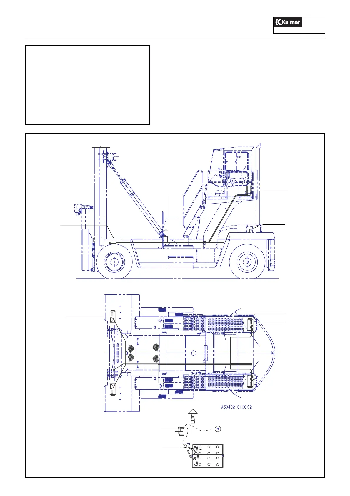
The system voltage is 24V and the supply is taken from two 12V
batteries connected in series and charged by an alternator
across electronic rectifying and voltage stabilisation circuits. .
The positive pole is connected across a main switch. The nega-
tive pole is connected to the chassis.
Warning lamps and instruments are clearly arranged on the in-
strument panel. The central electrical unit with fuses and relays
is located on the lower section of the cab’s rear wall.
IMPORTANT!
Always open the main switch when-
ever work is to be carried out on the
electrical system, if the truck is to
remain idle for some time and when-
ever welding work is to be carried out
on the truck.
1
2
3
4
5
5
5
6
7
1. Driving lights
2. Washer fluid container
3. Electrical central
4. Rear lights
5. Position lights
6. Main switch
7. Battery