DCE80-100E
Technical Handbook
Engine Cummins QSB 5.9
Description
43
P.Group 30
TDCE01
04GB
Turbocharger
The turbocharger supplies more air to the combustion chambers
than the engine would be capable of drawing naturally. This ena-
bles the engine to burn more fuel which, in turn, increases the en-
gine output.
The turbocharger consists of a turbine wheel and a centrifugal
compressor impeller, each with a separate casing but mounted
on a common shaft.
The exhaust gases provide the energy necessary for driving the
turbine wheel which, in turn, drives the compressor.
The turbocharger is lubricated and cooled by the lubricating oil
from the engine.
Intercooler
In intercooling, the air that has been compressed and heated by
the turbo is cooled in an intercooler.
The intercooler increases the oxygen supply for combustion so
allowing the injected fuel to be burnt more effectively whilst re-
ducing fuel consumption as well as the level of exhaust emission.
Intercooling also reduces the thermal stressed on the engine, in-
creasing durability and reducing oil consumption
The intercooler is of the water-to-air type and integrated with the
radiator and the gearbox oil cooler.
Inlet manifold heater
Before the air is admitted into the combustion chamber, it flows across
an electrically heated starting element. This heats the intake air suffi-
ciently for the engine to start at low ambient temperatures. The starter
heater is automatically controlled through an electronic control
module.
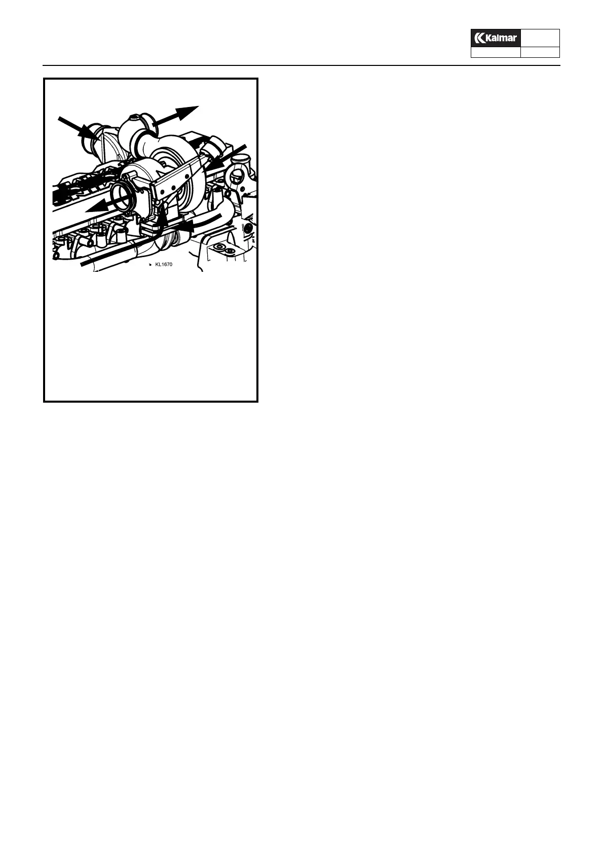
1. Exhaust gases to the silencer
2. Compressed air to the intercooler
3. Exhaust gases from the engine
4. Air from the filter
5. Intake air from the intercooler
Turbocharger
5
3
2
1
4
3