DCE80-100E
Technical Handbook
Main hydraulics
Service
17
P.Group 70
TDCE01
04GB
Checking of pressures and settings,
system with separate side-lift hydraulics
1. When making the following tests, use a manometer with a
hose of suficcient length so as the reading can be made from
inside the operator’s cab.
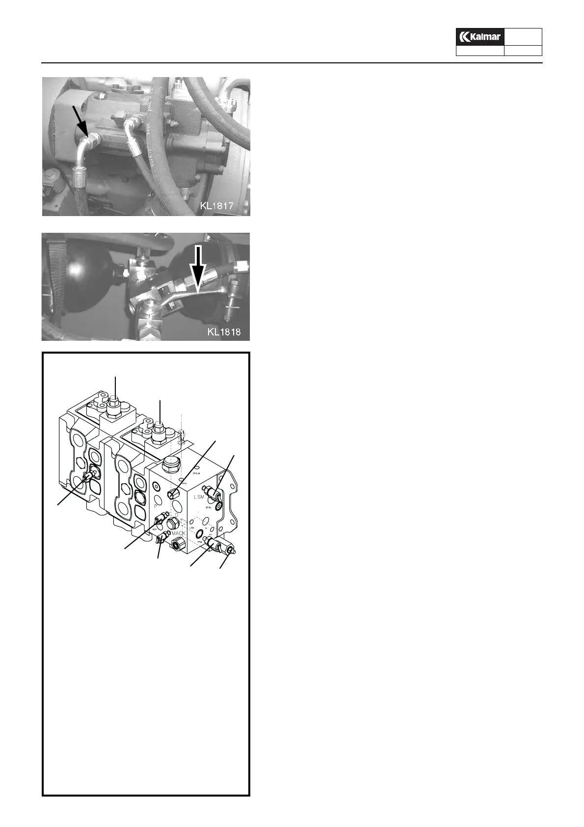
2. Unscrew the connection at A on the variable pump and fill the
pump with hydraulic oil. Reconnect A.
3. Open the accumulator evacuating valve 42 and start the en-
gine.
4. Stop the engine to check that the stopping device is working.
Pressure, accumulator charging
5. Connect the manometer to test outlet 10.
6. Start the engine and let it run at 1200 r/min.
7. Close the accumulator charging valve 42.
8. The pressure in 10 should increase from the accumulator
pre.charging pressure up to the charging pressure according
to the hydraulic plate. Adjust if necessary on adjustment
screw 1.
Pressure Steering system
9. Stop the engine and slightly lift up the machine to relieve the
steering wheels.
10.Connect th manometer to test outlet 15.
11.Start the engine and let it run at 1200 r/min
12.Check the steering pressure in test outlet 15. Turn the stee-
ring wheel in one direction. Let the steering spindle go to stop
and read the pressure. The pressure reading should be accor-
ding to the hydraulic plate. Adjust if necessary on adjustment
screw 2.
Pressure servo system
13.Connect the manometer to test outlet 8. The pressure reading
should be 35±5 bar. Tis pressure cannot be adjusted.
Pressure working hydraulics, TILT and LIFT
14.Connect the manometer to test outlet 9. Operate the tilt func-
tion until stop and read the manometer. The pressure reading
should be according to the hydraulic plate. The pressure
reading should also be equal to the pressure in outlet 14, see
next item. Justera vid behov på justerskruv 13.
15.Connect the manometer to test outlet 14. The pressure is set
individually for each truck and is stated in the delivery specifi-
cation and the hydraulic plate. The pressure should be set so
that the truck can only just lift its rated load at the appropriate
load centre. The pressure should be equal to the pressure in
outlet 9. Adjust if necessary on adjustment screw 12.
16.The adjusting screw must be sealed after making any adjust-
ment.
..to be continued next page.
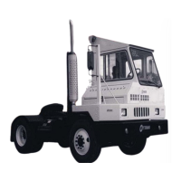
A
42
KL1834
12
13
2
14
9
10
8 1
15
(Numreringen gemensam med Hydraulschema
A44866.0100)
1 Justerskruv, ackumulatorladdningstryck
2. Justerskruv, tryck i styrsystem
8 Mätuttag servotryck 35±5 bar, ej justerbart
9 Mätuttag, TILT
Skall ha samma tryck som 14
10 Mätuttag, ackumulatorladdning
12 Justerskruv, huvudtryckbegränsnings-
ventil LYFT. Ställs lika med 13
13 Justerskruv, huvudtryckbegränsnings-
ventil TILT. Ställs lika med 12
14 Mätuttag, LYFT
Skall ha samma tryck som 9
Mät- och justeringspunkter,
ventilblock och huvudventil