ULTRAFLOW®54(H)/(J)
KamstrupA/S∙TechnicalDescription∙5512‐1554_J1_GB_04.2018
21
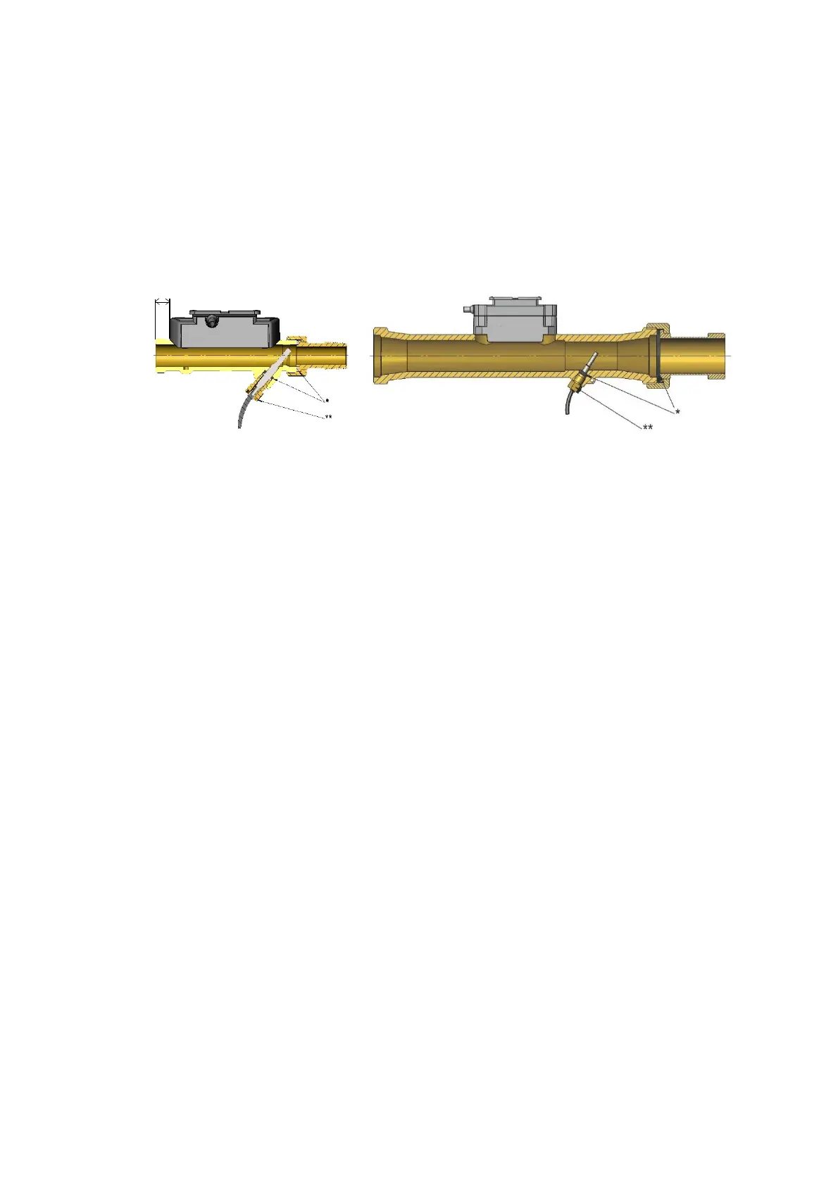
Mounting of couplings, and short direct sensor mounted in ULTRAFLOW
®
– see Figure 9 below.
The short direct sensor from Kamstrup may be installed in PN16 installations only. The blind plug, which is mounted
in ULTRAFLOW
®
from the factory, can be used in connection with both PN16 and PN25.
The flow sensor can be used in both PN16 and PN25 installations and is available with either PN16 or PN25 marking
as required.
Enclosed couplings, if any, are only intended for PN16. Suitable PN25 couplings must be used in PN25 installations.
In connection with G3/4x110 mm and G1x110 mm it must be checked that the thread run-out is sufficient.
Type 65-5-XXHX-XXX Type 65-5-XXJX-XXX
Figure 9. ULTRAFLOW
®
54 (H)/(J) with coupling and short direct sensor
(*Gaskets; **Torque value approx. 4 Nm).
12 mm

 Loading...


