ULTRAFLOW®54(H)/(J)
40
KamstrupA/S∙TechnicalDescription∙5512‐1554_J1_GB_04.2018
The calculation above is simplified, as it does not consider flow profiles. Flow profiles generally influence the
measurand, which, in our case, is the transit time difference. Flow sensors are therefore properly adjusted according
to different Reynolds numbers characterizing the flow, i.e. in praxis for different flow (volume flow rate) and
temperature. However, in order to cover different flow profiles with the ultrasonic signal as best as possible
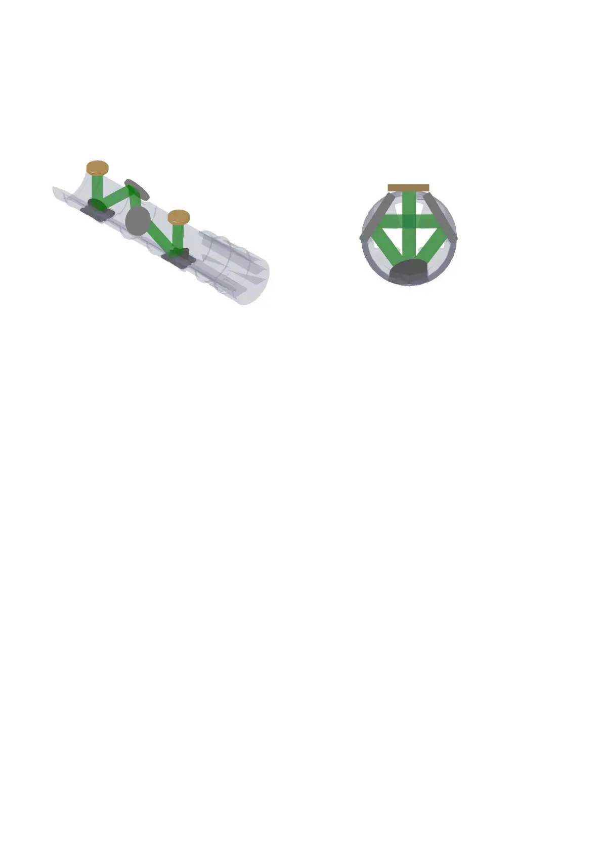
Kamstrup utilizes a triangular sound path as illustrated in Figure 35 from 2 perspectives, for larger ULTRAFLOW
®
54
flow sensors (qp 3.5…10 m
3
/h).
(a) (b)
Figure 35: Signal path inside ULTRAFLOW
®
54 (J) (q
p
3.5…10 m
3
/h) shown from the side (a) and when looking into
the measuring pipe (b). Sound signals are transmitted by the transducers via 4 reflectors. When looking into the
measuring pipe (b) the signal is reflected along a triangular path.

 Loading...


