Keysight 33210A User’s Guide 7
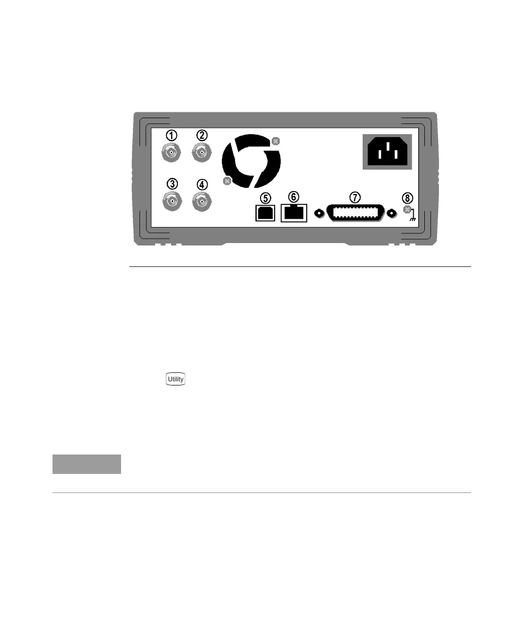
The Rear Panel at a Glance
Use the
menu to:
– Select the GPIB address (see Chapter 2).
– Set the network parameters for the LAN interface (see Chapter 2).
– Display the current network parameters (see Chapter 2).
1
External 10 MHz Reference Input
Terminal
(Option 001 only)
.
2
Internal 10 MHz Reference Output
Terminal (Option 001 only)
.
3 External Modulation Input Terminal
4 Input:
External Trigger/Burst Gate
Output: Trigger Output
5 USB Interface Connector
6 LAN Interface Connector
7 GPIB Interface Connector
8 Chassis Ground
The External and Internal 10 MHz Reference Terminals (1 and 2, above) are
present only if Option 001, External Timebase Reference, is installed. Otherwise,
the holes for these connectors are plugged.